


Dear all,
I am design the HW of F28388, I found some mismatch between controlCARD and datasheet:
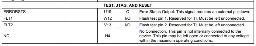
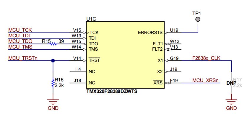
1. The ERRORSTS pin. The datasheet said this signal requires an external pulldown, but the controlCARD SCH shows the pin is left unconnected. I see in F2837x datasheet the ERRORSTS have internal pulldown, so no such external pulldown is required, is there any change for F2838x?
2. The VSSOSC pin. Datasheet said when using an external crystal do not connect this pin to the board ground, instead, connect it to the ground reference of the external crystal oscillator circuit. I see F2837x ref design do as this requirement, but in F28388 controlCARD, the VSSOSC connect direct to GND. Do we need to connect the VSSOSC and crystal ground together to the board GND?

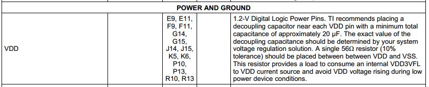
3. VDD pin. Datasheet said a single 56Ω resistor (10% tolerance) should be placed between between VDD and VSS, this resistor provides a load to consume an internal VDD3VFL to VDD current source and avoid VDD voltage rising during low power device condition. But in controlCARD, we cannot see this resistor. Do we need this resistor?
Thanks.

