This thread has been locked.

If you have a related question, please click the "Ask a related question" button in the top right corner. The newly created question will be automatically linked to this question.

TMS320F28069: I2CEMDR register and clock stretching

Part Number: TMS320F28069


Hi expert,

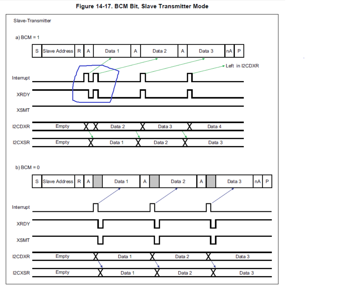
I'd like to know the function of I2CEMDR register and its BCM bit. In IIC slave mode, is that bit a switch for enabling or disabling IIC clock stretching?

From 14.2.7 Clock Synchronization in TRM, I think F28069 device can stretch IIC clock in slave mode by default, am I correct?

If some case we set BCM to 1 and device is in IIC slave mode, will it stretch SCL to 0 if not data is put into I2CDXR in time?

Please help with these three questions.

Thanks

Sheldon

  • Hi Sheldon,

    Please review Figure 14-16 'Backwards Compatibility Mode Bit, Slave Transmitter' of the device TRM for a timing diagram of what the BC bit does. I don't believe it's related to clock stretching, but will need to further check.

    http://www.ti.com/lit/spruh18

    Sheldon He said:
    From 14.2.7 Clock Synchronization in TRM, I think F28069 device can stretch IIC clock in slave mode by default, am I correct?

    I'm not certain on this, let me confirm and get back to you. There are situations documented in the I2C TRM chapter where the SCL line is held low, but I don't know if active clock stretching is an included function.

    Hope to get back to you tomorrow.

    Best,

    Kevin

  • Hi Kevin,

    Thanks

    Looking forward to your updates.

    Sheldon

  • Hi Kevin,

    Another question related to the BCM bit here. When BCM set to 1, will the situation in blue cycle 100% happen? 

    Take PMBus as an example, enable AAS, SCD, XRDY and RRDY interrupt, when master read the slave, will the slave generated two XRDY in 100% as shown in the blue cycle? We need this for when only one XRDY is generated, underflow happens and SCL be pulled low.

    Thanks

    Sheldon

  • Hi Sheldon,

    I'm still working on getting answers to your previous questions. What are you meaning by 'blue cycle' in your latest post?

    Best,

    Kevin

  • Hi Sheldon,

    Regarding the BC bit...

    I am not aware of the reason why the BC bit was included. But, based on what I see in the timing diagram in the TRM chapter. the BC bit controls the behavior of when the XRDY bit is set and when the XRDY interrupt gets generated. When BC=1 it helps to avoid underflow condition whereas when BC=0, it creates underflow condition each time a transmit ready is generated.

    Still working to confirm clock stretching support.

    Best,

    Kevin

  • Hi Kevin,

    Sorry for forgetting the graph here.

    My customer cares about this because they enabled mulitple interrupt. So of them may confilit the first interrupt in the blue cycle and cause error in their software logic. Could you help me confirm that when these four interrupts I mentioned are enabled, the two interrupt in the blue cycle can be guaranteened?

    Thanks

    Sheldon

  • Hi Kevin,

    Any update from your side?

    Thanks

    Sheldon

  • Hi Sheldon,

    Sheldon He said:
    Could you help me confirm that when these four interrupts I mentioned are enabled, the two interrupt in the blue cycle can be guaranteened?

    Yes, if BC is set to 1 and the device is configured as a slave transmitter, then the XRDY state and interrupt will match what is shown in the figure.

    Regarding clock stretching, when the the I2C module is configured as a slave it can hold the SCL line low between bytes while intervention by the device is needed for processing. This is documented in table 14-2 "Operating Modes of the I2C Module".

    Best,

    Kevin