This thread has been locked.

If you have a related question, please click the "Ask a related question" button in the top right corner. The newly created question will be automatically linked to this question.

LAUNCHXL-F28379D: I2C Sends slave addr, then immediately ends with NACK

Part Number: LAUNCHXL-F28379D
Other Parts Discussed in Thread: C2000WARE, TMS320F28379D

Thanks in advance for the help.

I've loaded the C2000Ware "i2c_ex3_external_loopback" example into CCS7 and uploaded it to the LaunchXL-F28379D hardware.

The example code expects to use GPIO32 & 33 for I2CA and 34 & 35 for I2CB, but the LaunchXL-F28379D hardware doesn't expose all of those pins.  As a work-around, I used GPIO104 & 105 for I2CA and 40 & 41 for I2CB.

Here's the init code changes:

    //
    // Initialize GPIOs 32 and 33 for use as SDA A and SCL A respectively
    //
/*    GPIO_setPinConfig(GPIO_32_SDAA);
    GPIO_setPadConfig(32, GPIO_PIN_TYPE_PULLUP);
    GPIO_setQualificationMode(32, GPIO_QUAL_ASYNC);

    GPIO_setPinConfig(GPIO_33_SCLA);
    GPIO_setPadConfig(33, GPIO_PIN_TYPE_PULLUP);
    GPIO_setQualificationMode(33, GPIO_QUAL_ASYNC);
*/
    GPIO_setPinConfig(GPIO_104_SDAA);
    GPIO_setPadConfig(104, GPIO_PIN_TYPE_PULLUP);
    GPIO_setQualificationMode(104, GPIO_QUAL_ASYNC);

    GPIO_setPinConfig(GPIO_105_SCLA);
    GPIO_setPadConfig(105, GPIO_PIN_TYPE_PULLUP);
    GPIO_setQualificationMode(105, GPIO_QUAL_ASYNC);

    //
    // Initialize GPIOs 34 and 35 for use as SDA B and SCL B respectively
    //
/*    GPIO_setPinConfig(GPIO_34_SDAB);
    GPIO_setPadConfig(34, GPIO_PIN_TYPE_PULLUP);
    GPIO_setQualificationMode(34, GPIO_QUAL_ASYNC);

    GPIO_setPinConfig(GPIO_35_SCLB);
    GPIO_setPadConfig(35, GPIO_PIN_TYPE_PULLUP);
    GPIO_setQualificationMode(35, GPIO_QUAL_ASYNC);
*/
    GPIO_setPinConfig(GPIO_40_SDAB);
    GPIO_setPadConfig(40, GPIO_PIN_TYPE_PULLUP);
    GPIO_setQualificationMode(40, GPIO_QUAL_ASYNC);

    GPIO_setPinConfig(GPIO_41_SCLB);
    GPIO_setPadConfig(41, GPIO_PIN_TYPE_PULLUP);
    GPIO_setQualificationMode(41, GPIO_QUAL_ASYNC);

Next, it seems the documentation for the LaunchXL-F28379D (VER:1.1) reverses the pins on J5 where GPIO40 & 41 connect.  The graphic in the "Meet the TMS320F28379D LaunchPad Development Kit" brochure shows "P41" at J5-49 and "P40" at J5-50.  However, when I trace the circuit out using the Gerber files in C2000Ware R1.1, the reverse is true.  P40 connects to J5-49 & P41 to J5-50.  As a result, instead of connecting "SCLA (GPIO33) to SCLB (GPIO35)" etc., I connected SCLA (GPIO105) to SCLB (GPIO41) etc.  (I found this while troubleshooting, because it wasn't working when connected the other way.)

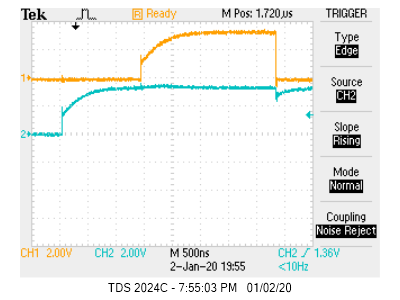
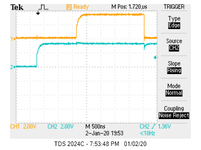
OK, now that that's out of the way, when I run the code, I see the slave being addressed on the I2C bus followed immediately by a NACK.  Nothing further happens.

The RXFFINT flag never gets set.  RXFFIENA enable bit is set.  I've confirmed the slave address is set to 0x3C.

It seems like the data never gets into the receive buffer of I2CB.

Question #1:  Where in the code is it sending the slave address?

Question #2:  Where in the code is it sending the NACK?

Question #3:  Do I have the I2C module configured appropriately?

Further, the codes runs long enough to increment the send array (sData) to 2,3, and then it enters the while loop, never to hear from the I2C module again.  rDataPoint never changes from 0.

I appreciate any help you can give.

  • Due to holidays, you can expect a response in the first week of Jan 2020.

  • Did you add _LAUNCHXL_F28379D to your predefined symbols as well? The controlCARD and LaunchPad have different speed external oscillators, so the _LAUNCHXL_F28379D is needed to change the PLL configuration to the expected 200 MHz, although I don't think this is the cause of the issue.

    1. The slave address is sent by the hardware as part of the transmission kicked off by the call to I2C_sendStartCondition() in the ISR.

    2. The code doesn't take any action to send a NACK. The hardware is generating this one.

    3. The default example works fine on the controlCARD, and I don't see any issues with the GPIO-related modifications you've made.

    I did find this forum post where someone has success overcoming a similar issue using an external pull up instead of relying on the device's internal one. Can you try that?

    Whitney

  • Also, could you explain how you arrived at the conclusion that "P40 connects to J5-49 & P41 to J5-50"? What was the difference in behavior? I toggled the GPIOs and watched the scope and it appeared to match the pin out stated in the User's Guide.

    Whitney

  • Hi Whitney,

    Thanks for the response.

    My apologies.  Upon closer examination, I see that GPIO40 (SDAB) is truly connected to J5-50 on the LaunchXL-F28379D.

    When I originally read it the wrong way, I swapped SDAB & SCLB from the correct pins to the incorrect ones.

    The behavior was identical either way.  The receive buffer never picked up any input.  On transmit, the master sent the slave address and end immedeiately with a nack.

    Here it is with the correct hookup:

    So, please accept my apology and ignore that portion of my post.  I will go review your other response and let you know what I find.

    Thanks, robin.

  • Hi Whitney,

    OK, if I add external pullups to SDAB & SCLB, then I get an ACK after sending the slave address.  But then, nothing else happens.

    However, if I set a breakpoint anywhere in the I2C_clearInterruptStatus() function, then it transmits and receives all data properly each time I hit the run button.  (Although I don't see a "stop").

    Regarding your answers to my previous questions:

    1. OK, understood.

    2. OK, understood.

    3. I can see that the I2C sends and returns are connected properly with the new GPIO assignments, but only with the breakpoints.

    Regarding predefined symbols, I had not included _LAUNCHXL_F28379D, but including it makes no difference.

    Ideas?

    Thanks again for your support.

  • Hi Whitney,

    Here's the breakdown of why I wasn't getting data throughput from transmit to receive:

    The risetime of the SCL and SDA was insufficient.  By adding pullup resistors to both lines, the rise time is now sufficient for the hardware to do its thing.

    Here are the SCL & SDA lines without external pull up resistors:

    And here they are with 2.2k pull-ups to 3.3V:

    After installing the pull-ups, I was still having problems with the data transfer.  After reloading the example code from scratch and making the necessary modifications listed in my original post, all transfers worked properly.

    The secondary problem was with code mod's I had made during debugging that I hadn't reverted back.

    This issue is now resolved.

    Thanks for the help!

  • Great! Thanks for the update.

    Whitney