This thread has been locked.

If you have a related question, please click the "Ask a related question" button in the top right corner. The newly created question will be automatically linked to this question.

CCS/TMS320F28035: Interleave PFC Ver.1.0 Project Tracing, software issue

Part Number: TMS320F28035
Other Parts Discussed in Thread: CONTROLSUITE

Tool/software: Code Composer Studio

Dear Sir,

1)     I have a “C2000 2 Phase Interleaved Power Factor Correction Kit” with “Piccolo F28035 Isolated controlCard”, and now is tracing the project of C:\ti\controlSUITE\development_kits\ILPFC_v1.0

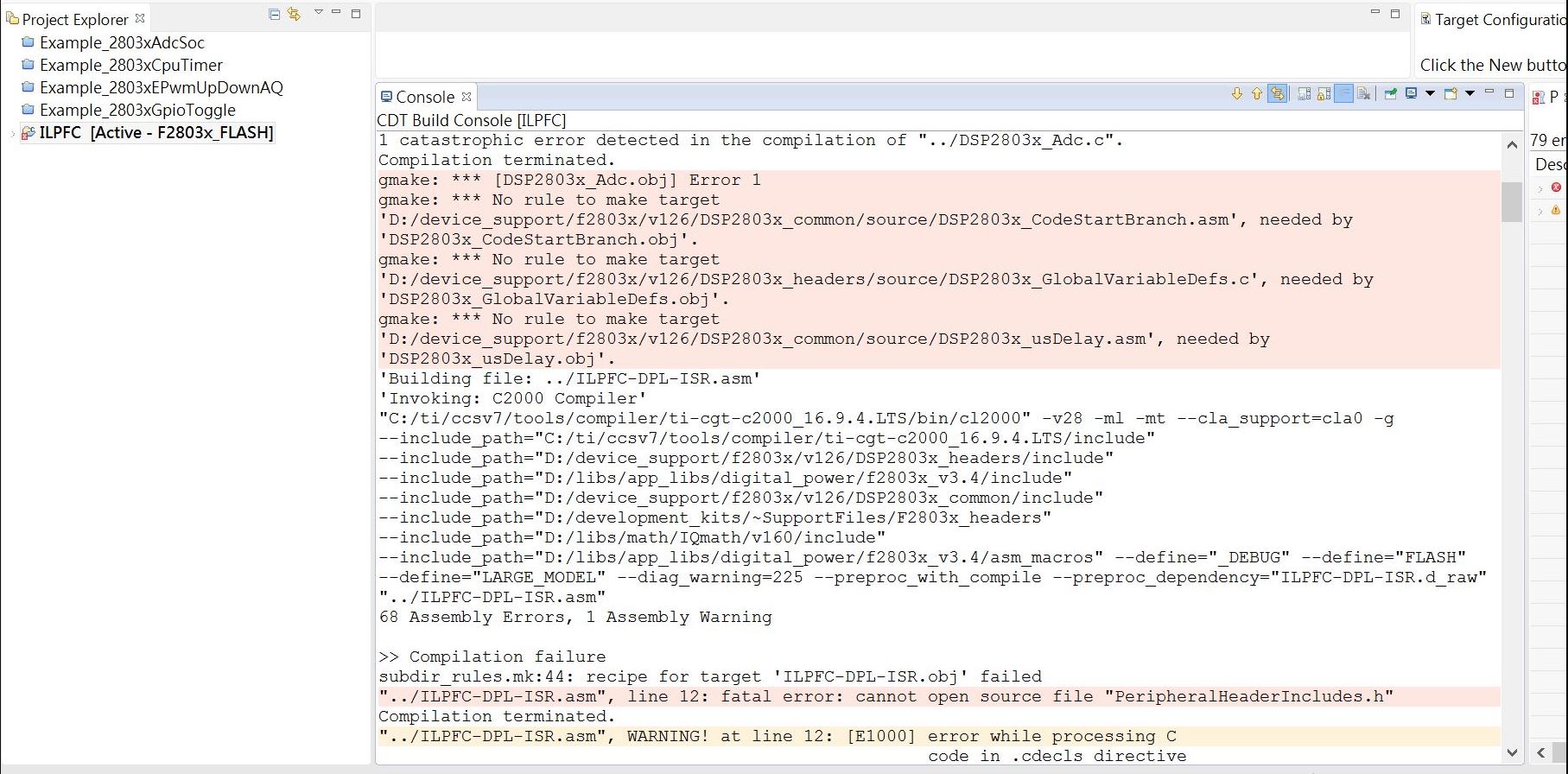
2)     To comment the program to Chinese traditional, I copied the whole ILFFC_v1.0 project directory and renamed it to ILPFC directory, then put it under D: \ ILPFC directory, then rebuilt, but the following errors occurred, how can I correct those errors?
How should I copy the directory so that I don't make any errors during rebuild?
3)  In ILPFC-Main.c.file, the number 10000.0 in lines 548 and 0.1 in line 549, what are meaning?

548    sine_mainsV.SampleFreq=_IQ15(10000.0);

549  sine_mainsV.Threshold=_IQ15(0.1);//(0.015);//(0.02);

4)  In the comment on line 563, why it need 8 times oversampling? And, on line 565, why it need Dummy reading?

5)   In lines 580 to 593, the current’s trigger sequence TrigSel [0] to TrigSel [11] is: EPWM3 → EPWM3 → EPWM4 → EPWM3 → EPWM4 → EPWM1 ​​→ EPWM2 → EPWM1 ​​→ EPWM2 → EPWM1 ​​→ EPWM1 ​​→ EPWM3. What does it mean? Can be change the Trigger sequence?

6)   About the ILPFC-Settings.h file in the ILPFC Ver. 1.0 project, Could you tell me in line 62 to line 67, what is meaning about 4095*4095 ?

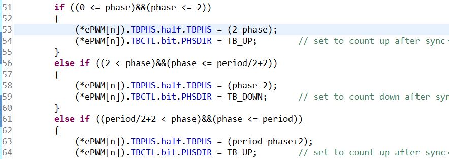
7)   About the PWM_2ch_UpDwnCnt_Cnt.c file, from line 51 to line 65, I can’t realize the meanings, could you explain for me ? specially in line 51, 56, and 61, what is the meaning in each line?
Thank you so much for your help
Best regard
Hung-Jin Chen

  • Hi Hung-Jin,

    Due to the US Holidays please expect a reply next week.

    Best Regards,

    Marlyn

  • Thank you for your concern and look forward to your response.

  • Hi Hung-Jin,

    2) It is due to the mismatch of the directory in the CCS. The project itself need some supporting files located in the controlSUITE/device support.. Two things you can do: a) you can reimport the project and select copy to workspace and change reference there. b) you can modify the reference directory in CCS by right clicking project name and select property/resource/linked resource and change the new routine where you paste the project.

    3. You can click SineAnalyzer2.h to see the comment and how those two value are used. They are used to do the sine wave analysis.

    4. 8 times over-sampling are needed to eliminate the noise impact and increase the sampling accuracy under DCM mode. The dummy reading is because sometimes ADC is not being able to properly handle the first conversion from idle predictably.  Most of our example code works around this by using SOC0 to "dummy sample" an ADC input (typically just the same ADC input as SOC1).  

    5. Each SOC has ChSel and TrigSel. So the sequence are matched with ChSel settings. Please take a look at the ADCSOC in the TRM for more details.

    6. That is because those values are used for Q24(2^24) calculations. 

    7. This is basically doing the phase shift based on different phase shift values under up-down count mode. You can draw a pic to understand different conditions. Please take a look at the counter compare submodule in PWM module in TRM. 

    Regards,

    Chen

  • Dear Mr. Chen,

    Thank you very much for your response. The following questions still need your help.

    1. What is the abbreviation for TRM in your last poster?

    2. On lines 357 to 359 of ILFFC_main.c, where are the initialization routines for Timer0 to Timer2?

    3. On the lines 580 to 593 of ILFFC_main.c, does the triggering sequence have any special significance?

    4. On line 599 of ILFFC_main.c, ADC_SOC_CNF (ChSel, TrigSel, ACQPS, 17, 0); I don’t understand the meaning of this line

    5. On lines 77 ~ 82 of DSP2803x_ADC.c, its AIO2 to AIO14 are set to 2, which is not planned as an analog input setting! Is it ?

    6. On line 211 of DSP2803x_ADC.c, AdcRegs.ADCSOCFRC1.all = 0x00FF; there is a trigger of SOC0-7, why is there no trigger of SOC8-15 before line 228?

    7. On lines 662 to 712 of ILFFC_main.c, when INCR_BUILD == 1, is there any reference software design thinking?

    8. On lines 717 to 793 of ILFFC_main.c, when INCR_BUILD == 2, is there any reference software design thinking?

    9. On lines 798 to 913 of ILFFC_main.c, when INCR_BUILD == 3, is there any reference software design thinking?

    Best Regards


    Hung-Jin Chen

  • Please see the reply below:

    1. What is the abbreviation for TRM in your last poster?

    Technical Reference Manual

    2. On lines 357 to 359 of ILFFC_main.c, where are the initialization routines for Timer0 to Timer2?

    I don't get your question. Are you referring to three lines of code below?

    CpuTimer0Regs.PRD.all = mSec1; // A tasks
    CpuTimer1Regs.PRD.all = mSec50; // B tasks
    CpuTimer2Regs.PRD.all = mSec10; // C tasks

    3. On the lines 580 to 593 of ILFFC_main.c, does the triggering sequence have any special significance?

    No.

    4. On line 599 of ILFFC_main.c, ADC_SOC_CNF (ChSel, TrigSel, ACQPS, 17, 0); I don’t understand the meaning of this line

    if you click and open this function, you will get it. It is setting up ADCSOC.

    5. On lines 77 ~ 82 of DSP2803x_ADC.c, its AIO2 to AIO14 are set to 2, which is not planned as an analog input setting! Is it ?

    Based on the code, correct.

    6. On line 211 of DSP2803x_ADC.c, AdcRegs.ADCSOCFRC1.all = 0x00FF; there is a trigger of SOC0-7, why is there no trigger of SOC8-15 before line 228?

    Will get back to you on this question.

    7. On lines 662 to 712 of ILFFC_main.c, when INCR_BUILD == 1, is there any reference software design thinking?

    8. On lines 717 to 793 of ILFFC_main.c, when INCR_BUILD == 2, is there any reference software design thinking?

    9. On lines 798 to 913 of ILFFC_main.c, when INCR_BUILD == 3, is there any reference software design thinking?

    What do you mean by "reference software design thinking"?

    Regards,

    Chen

  • Hi, Hung-Jin,


    Any updates to the thread above?

    Regards,

    Chen

  • Dear Chen,

    Thank you for your reply,

    1)     On lines 357 to 359 of ILFFC_main.c, or as following, there are only set the period of of Timer0 to Timer2.

    I can’t find the initialization code about Timer0 to Timer2.

    Could you please point out where is the initialization code ? (which file and line number ?)

    357 CpuTimer0Regs.PRD.all = mSec1; // A tasks
    358 CpuTimer1Regs.PRD.all = mSec50; // B tasks
    359 CpuTimer2Regs.PRD.all = mSec10; // C tasks


    2) On lines 680 of ILFFC_main.c,

    680 PWMDRV_2ch_UpDwnCnt_Duty1 = &DutyA;

    Although it is part of DPLib, I cannot find a link or reference between DutyA (line 231) and PWMDRV_2ch_UpDwnCnt_Duty1 (line 198). i.e., in which program, DutyA is written, and in which program, PWMDRV_2ch_UpDwnCnt_Duty1 is referenced?

    (I had already read the DPLib.PDF and Fig.5 of TIDU249.PDF, but I still could not trace the program’s sequence.)


    2)     On lines 691 of ILFFC_main.c, What does 80V/409V mean ?

    691 PFC_InvRmsSqr_VminOverVmax1=_IQ30(0.1956);        // 80V/409V


    3)     On lines 699 of ILFFC_main.c, What does 285V/80V mean ?

    699 PFC_ICMD_VmaxOverVmin1=_IQ24(3.00);             // 3.5625 <=> 285V/80V


    4)  On lines77 to 82 of DSP2803x_ADC.c It should be planned as the analog input of Vfb, but bit.AIO2 = 2, which means disable; may I ask, in which line of the program will it be enabled?

    77 GpioCtrlRegs.AIOMUX1.bit.AIO2 = 2;

    5) Continue to the previous question, I can’t find a program that ADCINB0 pin is configured as VN_fb.

    Best Regard

    Hung-Jin Chen

  • Hi Hung-jin,

    1. You can search for CpuTimer0Regs by using Ctrl+H. 

    2. Please take a look at PWMDRV_2ch_UpDwnCnt.asm

    3. That is Vin/Vmax.

    4 and 5. Please search for DeviceInit.

    Thanks.

    Regards,

    Chen

  • Dear Mr. Chen,
    About the Q1 on last thread, I still can not find the initialization code of timer0 to timer2.

    Could you please point out the filename and the line number of timer0 to timer2 for me ?

    Thanks.

    Regards,

    Hung-Jin

  • Hi Hung-Jin,

    CpuTimer0Regs is defined in DSP2803x_GlobalVariableDefs.c line 64.

    There is no other initialization code. This is just to set timer period.

    Regards,

    Chen

  • Dear Mr. Chen,

    Thank you anyway.

    Regards

    Hung-Jin Chen