This thread has been locked.

If you have a related question, please click the "Ask a related question" button in the top right corner. The newly created question will be automatically linked to this question.

CCS/DRV8312-69M-KIT: Error while debugging

Part Number: DRV8312-69M-KIT
Other Parts Discussed in Thread: DRV8312, MOTORWARE

Tool/software: Code Composer Studio

We are referring "Trapezoidal Control of BLDC Motors Using Hall Effect Sensors" pdf. We have performed all the levels(all levels were performed fine).

But now, when we give supply to kit, a red LED is glowing (LED6 on the kit ) .

All connections are fine.

Also, after building the code (any level) when try to flash the board from CCS it is throwing error as attached below.

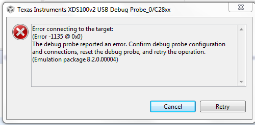
Can you let us know the resolution.

Regards.

  • Shivanjali, 

    Please check the .ccxml file and see if the debugger you are using is compatible with the one specified in that file. 

    Thanks,

    Shantanu

  • Hi Shantanu,

    We checked the .ccxml file, it is the same file which we were using earlier and this file was working fine.

    Debugger is also compatible.

    When we are giving supply to the kit, red LED (LED6 on the kit) is glowing (which indicates that fault is present). How to identify that fault? 

    Also, how to remove that fault?

    While flashing the code the same error is coming as mentioned in the above query. (Error connecting to the target:Error -1135 @ 0x0)

    (Earlier all levels were performed and they were working properly).

  • Hi,

    Thanks for your support. 

    The work is having high priority but we have been stuck due to presence of fault on the kit.(Query as mentioned above)

    Could you please provide us the contact details, as its urgent.

  • Hi Shantanu,

    Please let us know if there is any update regarding above query, as work is on high priority.

    Also if any document is available for Reset cause of DRV8312 kit do let us know.

    Thank You!

  • You might take a look at the following links that should help you. And make sure that the power supply for the C2000 device is well on the controlCard and the device is not damaged or locked by programming a wong CSM code as well.

    https://processors.wiki.ti.com/index.php/XDS100#Troubleshooting

    http://software-dl.ti.com/ccs/esd/documents/ccsv7_debugging_jtag_connectivity_issues.html

  • Is there any specific process to verify that the device is damaged or not ?

    If any document is available for it, do let us know.

    Thank You !

  • Please refer to the following links or you might try to connect other controlCards on the EVM if you have. If the connection is ok on other controlCards, that means your controlCard is damaged.

    https://e2e.ti.com/support/microcontrollers/c2000/f/171/t/539864

    https://e2e.ti.com/support/microcontrollers/c2000/f/171/p/798297/2961406

  • Hi, 

    We referred the above links, but our problem is not resolved.

    For your reference, here is my JTAG scan test results:

    [Start: Texas Instruments XDS100v2 USB Debug Probe_0]

    Execute the command:

    %ccs_base%/common/uscif/dbgjtag -f %boarddatafile% -rv -o -F inform,logfile=yes -S pathlength -S integrity

    [Result]


    -----[Print the board config pathname(s)]------------------------------------

    C:\Users\16990\AppData\Local\TEXASI~1\CCS\
    ccs910\0\0\BrdDat\testBoard.dat

    -----[Print the reset-command software log-file]-----------------------------

    This utility has selected a 100- or 510-class product.
    This utility will load the adapter 'jioserdesusb.dll'.
    The library build date was 'Jun 3 2019'.
    The library build time was '15:24:38'.
    The library package version is '8.2.0.00004'.
    The library component version is '35.35.0.0'.
    The controller does not use a programmable FPGA.
    The controller has a version number of '4' (0x00000004).
    The controller has an insertion length of '0' (0x00000000).
    This utility will attempt to reset the controller.
    This utility has successfully reset the controller.

    -----[Print the reset-command hardware log-file]-----------------------------

    The scan-path will be reset by toggling the JTAG TRST signal.
    The controller is the FTDI FT2232 with USB interface.
    The link from controller to target is direct (without cable).
    The software is configured for FTDI FT2232 features.
    The controller cannot monitor the value on the EMU[0] pin.
    The controller cannot monitor the value on the EMU[1] pin.
    The controller cannot control the timing on output pins.
    The controller cannot control the timing on input pins.
    The scan-path link-delay has been set to exactly '0' (0x0000).

    -----[The log-file for the JTAG TCLK output generated from the PLL]----------

    There is no hardware for programming the JTAG TCLK frequency.

    -----[Measure the source and frequency of the final JTAG TCLKR input]--------

    There is no hardware for measuring the JTAG TCLK frequency.

    -----[Perform the standard path-length test on the JTAG IR and DR]-----------

    This path-length test uses blocks of 64 32-bit words.

    The test for the JTAG IR instruction path-length failed.
    The JTAG IR instruction scan-path is stuck-at-ones.

    The test for the JTAG DR bypass path-length failed.
    The JTAG DR bypass scan-path is stuck-at-ones.

    -----[Perform the Integrity scan-test on the JTAG IR]------------------------

    This test will use blocks of 64 32-bit words.
    This test will be applied just once.

    Do a test using 0xFFFFFFFF.
    Scan tests: 1, skipped: 0, failed: 0
    Do a test using 0x00000000.
    Test 2 Word 0: scanned out 0x00000000 and scanned in 0xFFFFFFFF.
    Test 2 Word 1: scanned out 0x00000000 and scanned in 0xFFFFFFFF.
    Test 2 Word 2: scanned out 0x00000000 and scanned in 0xFFFFFFFF.
    Test 2 Word 3: scanned out 0x00000000 and scanned in 0xFFFFFFFF.
    Test 2 Word 4: scanned out 0x00000000 and scanned in 0xFFFFFFFF.
    Test 2 Word 5: scanned out 0x00000000 and scanned in 0xFFFFFFFF.
    Test 2 Word 6: scanned out 0x00000000 and scanned in 0xFFFFFFFF.
    Test 2 Word 7: scanned out 0x00000000 and scanned in 0xFFFFFFFF.
    The details of the first 8 errors have been provided.
    The utility will now report only the count of failed tests.
    Scan tests: 2, skipped: 0, failed: 1
    Do a test using 0xFE03E0E2.
    Scan tests: 3, skipped: 0, failed: 2
    Do a test using 0x01FC1F1D.
    Scan tests: 4, skipped: 0, failed: 3
    Do a test using 0x5533CCAA.
    Scan tests: 5, skipped: 0, failed: 4
    Do a test using 0xAACC3355.
    Scan tests: 6, skipped: 0, failed: 5
    Some of the values were corrupted - 83.3 percent.

    The JTAG IR Integrity scan-test has failed.

    -----[Perform the Integrity scan-test on the JTAG DR]------------------------

    This test will use blocks of 64 32-bit words.
    This test will be applied just once.

    Do a test using 0xFFFFFFFF.
    Scan tests: 1, skipped: 0, failed: 0
    Do a test using 0x00000000.
    Test 2 Word 0: scanned out 0x00000000 and scanned in 0xFFFFFFFF.
    Test 2 Word 1: scanned out 0x00000000 and scanned in 0xFFFFFFFF.
    Test 2 Word 2: scanned out 0x00000000 and scanned in 0xFFFFFFFF.
    Test 2 Word 3: scanned out 0x00000000 and scanned in 0xFFFFFFFF.
    Test 2 Word 4: scanned out 0x00000000 and scanned in 0xFFFFFFFF.
    Test 2 Word 5: scanned out 0x00000000 and scanned in 0xFFFFFFFF.
    Test 2 Word 6: scanned out 0x00000000 and scanned in 0xFFFFFFFF.
    Test 2 Word 7: scanned out 0x00000000 and scanned in 0xFFFFFFFF.
    The details of the first 8 errors have been provided.
    The utility will now report only the count of failed tests.
    Scan tests: 2, skipped: 0, failed: 1
    Do a test using 0xFE03E0E2.
    Scan tests: 3, skipped: 0, failed: 2
    Do a test using 0x01FC1F1D.
    Scan tests: 4, skipped: 0, failed: 3
    Do a test using 0x5533CCAA.
    Scan tests: 5, skipped: 0, failed: 4
    Do a test using 0xAACC3355.
    Scan tests: 6, skipped: 0, failed: 5
    Some of the values were corrupted - 83.3 percent.

    The JTAG DR Integrity scan-test has failed.

    [End: Texas Instruments XDS100v2 USB Debug Probe_0]

    Could you please suggest us the resolution for the same.

  • Are you the first time to use the controlCard? Or the controlCard worked well before?

    Please check if the switches on the controlCard have been set correctly as the guide. and follow the steps in the links recommended above to check the emulator again.

    Download motorWare as the link http://www.ti.com/tool/motorware, and find the guide in the folder as below.

    \ti\motorware\motorware_1_01_00_18\docs\boards\control\f2806x\docs

    If you still met the connection failed error, unfortunately, that means the controlCard may be damaged.