This thread has been locked.

If you have a related question, please click the "Ask a related question" button in the top right corner. The newly created question will be automatically linked to this question.

TMS320F280049C: MCU Initialization Problem

Part Number: TMS320F280049C


I have observed the following result with my texas MCU TMS320F280049C:-

The gpio port pins are pulled up after power on on random basis (80%) and proper power on (20% of the time).

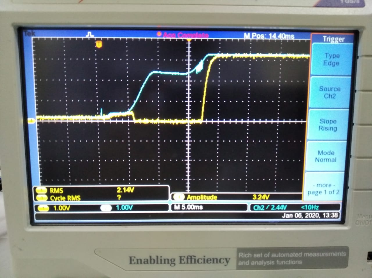
The MCU is not initialized properly although all the necessary voltages i.e. (external 3V3 and internally generated 1V2 are both generated as verified on DSO in both proper and improper turn on sequence)

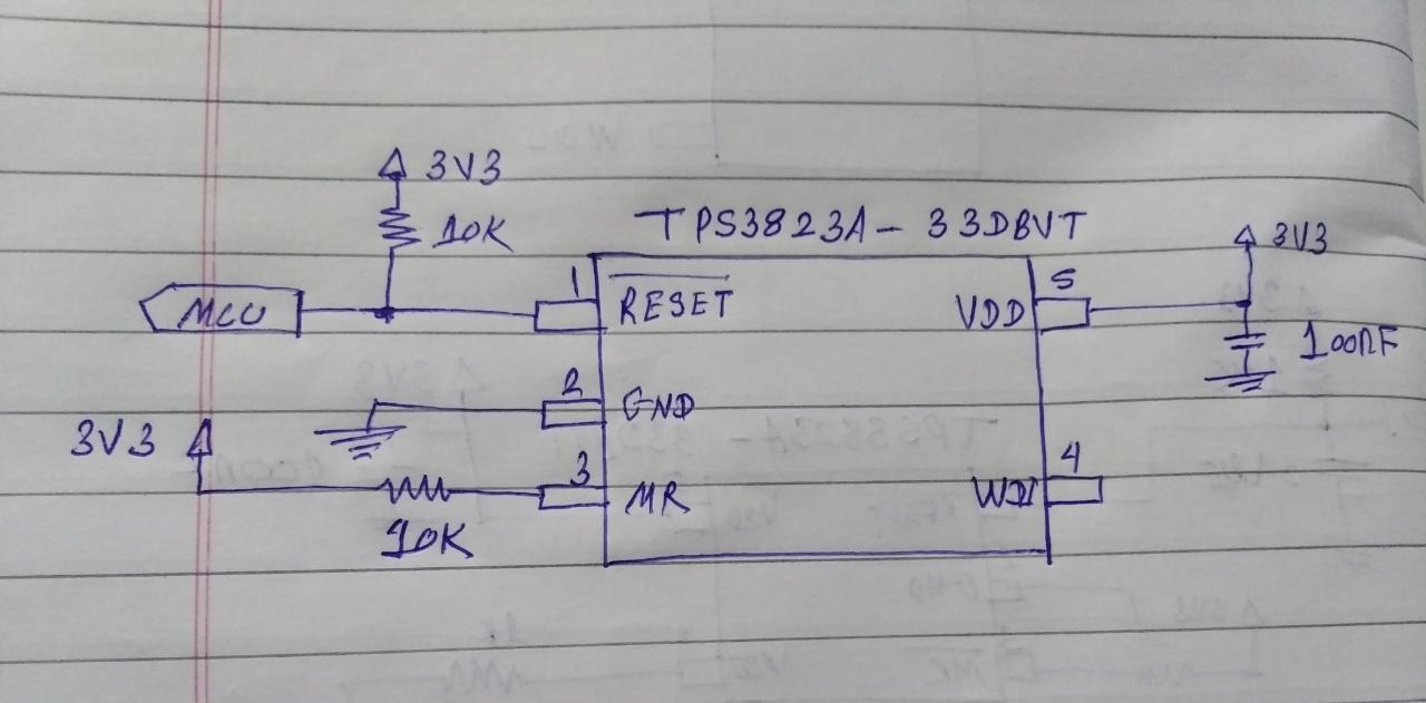
Also the reset pin circuit diagram is as per the recommended values by TI Datasheet. 

I have used internal clock and hence am grounding the X1 pin via a pull down resistor of 1k.

Vfbsw(GPIO22) & Ysw(GPIO23) are both not connected. 

What seems to be the root of this issue ??

Kindly reply ASAP as our project deadlines are getting affected by this problem.

Regards, 

Bhaskar.

  • Bhaskar,

    What does your code do in the main function? 

    Nima

  • I have initialized the ADC, PWM, , timer, external interrupts, gpio port pins, and disabled the watchdog timer. 

    Apart from that my application code is running.

    Regards, 

    Bhaskar

  • As a trial suggested by Vikas Chola (India Texas Instruments), I have tested the gpio port pin no. 5 toggling on my controller board.

    The port pin is toggled in debug mode. But controller remains in hang mode i.e. MCU does not initialize properly, when run out of debug mode. I have run the code from flash memory (changed in the example code). I have used internal osc. as a clock.

    I am attaching the schematic of my board. Please tell me if there seems to be any problem with the it.

    Regards,

    Bhaskar.

  • These are the 2 trials which I took:-

    1. Linear Power Supply

    The reset waveform is rising as follows and the port toggling code is working. Below image is of 3V3 rise (blue) against reset pin waveform (yellow)

    2. SMPS 

    When SMPS is used, I get the following waveform and the MCU is in hang mode i.e. all ports pulled high condition, and the controller does not perform toggling function.

    Regards, 

    Bhaskar.

  • How do you know you application is correctly downloaded to flash and that you ARE BOOTING from flash?

  • When I replace the reset pin XRS capacitor with a switch for manual reset, it resets the MCU every time I press the switch and my application code runs fine which means my code has been properly downloaded to MCU memory.

    Regards,

    Bhaskar.

  • Hi Bhaskar,

    Vinaykumar singh said:
    When SMPS is used, I get the following waveform and the MCU is in hang mode i.e. all ports pulled high condition, and the controller does not perform toggling function.

    Even the EVM schematic has not identified XRSn into MCU reset even exists, search for 1/2 hour TI schematic.

    Assume your SMPS is the TPS3702CX33DDCR not shown in your schematic? Do you think the SMPS is causing a NMI fault? 

    One custom PCB of many run or a single board only? Have you rang out MCU pin to pin via DMM and used 10x magnification for a visual inspection between MCU pins?

  • Finally find schematic small yellow block left side 3rd page XRSn input and block has FLT1 pin 48, FLT2 pin 49 must indicate type of fault condition. 

  • Hi Gl, 

    I have not used TPS3702CX33DDCR in my schematic.

    On many boards (linear supply and smps both different pcbs), and I'm getting the same results.

    The Mcu pin to pin does not ring on DMM which I had checked already, and i have used magnifying 10x lens (along with lights) for visual inspection.

    Regards,

    Bhaskar.

  • Perhaps you have isolated the problem to SMPS raising MCU reset to rapidly? Ok SMPS is a switch mode power supply. At times we see similar issue from linear 24vdc supply powering Rohm 5v buck into TI 3v3 LDO powers VDD TM4C1294 MCU. 

    So Rohm buck has 47uF ceramic on VCC input series with ferrite SMD stack to feed 5v buck and stack two 10uf ceramic on output. On your MCU SMPS is charging the +3v3 into reset pin two rapid of rise time.

  • Hi Gl,

    1.Are you suggesting that there is a problem with the Power on reset functionality of tms320f280049m??

    2.I am already using the max rated values as recommended datasheet (shown in the schematic of 10 kOhm pullup and 0.1 uF capacitor)

    3. Should I increase it further and delay the reset hold time??

    Regards,

    Bhaskar.

  • 1. The SMPS and 3v3 are banging up to rail extremely fast, well before MCU is stable for reset. Stacking caps on buck down output, slows down rise to VDD peak . Are you using the 49c DC/DC onboard buck regulator for 3v3?

    Also look at the 49c launch pad schematic, it has series 3v3 into 60R=VDDA  & VDDIO_SW=220R for POR reason? Build guide suggest 20uf bulk cap VDD but the reset POR rise time is critical in many of TI MCU classes.

    3. Is not the linear supply doing just that by adding roll off to reset pin rise time?

  • Hi TI team, 

    I have been able to delay the rise of reset pin (yellow) against 3V3 (blue) waveform.

    Still the MCU hangs and outputs high to GPIO pins.  

    I have used the recommended TPS3823A connections(pic attached below).

    What seems to be the case here??

  • Vinaykumar singh said:
    I have used the recommended TPS3823A connections(pic attached below).

    You never answer question how 3v3 originates via bucking method or LDO. If you use any buck regulator for 3v3 VDD it must conform to POR rise time specifications. I have not checked the 49c technical reference PDF but suspect such timing diagrams do exist. 

    Have you slowed down the SMPS rise time via 3v3 buck source as first suggested?

    Does the linear supply work with TPS as before it did even without TPS?

  • Hi Gl,

    3V3 is generated via buck method.

    It seems that you have not seen the waveforms pics clearly, it takes almost 500 miliseconds for smps waveform to stabilize. How much more should I increase the rise time.

    I am taking trials on 3v3 linear supply.

    Regards,

    Bhaskar.

  • Greetings TI team,

    Please reply on this issue as it is still not solved.

    Regards,

    Bhaskar.

  • Vinaykumar singh said:
    it takes almost 500 miliseconds for smps waveform to stabilize

    TMS320F280049c Datasheet 5.9.2 .2

    Page 69 Fig.28 show TW(RSL1) 100us after all supplies are stable Table 5-11. And XRSn must remain low for 100us after VDD, VDDIO, VDDA reach 100% +3.3v.

    The scope captures seem to show XRSn rising edge going high with 3v3 at 70% or so from my last review. Would not 500ms delay between 3v3 being stable to XRSn be out of tolerance? 

  • Looking at the 3v3 rise up to +1.75v >250ms then goes straight up to 3v3. Does you SMPS have an EN pin you can remove step up to 1.75v? We do that with Rohm buck down to +5v and enable pin threshold near +3.5v based on input to VS rise time. So the 3v3 LDO has clean rise up to VDD without any steps.