This thread has been locked.

If you have a related question, please click the "Ask a related question" button in the top right corner. The newly created question will be automatically linked to this question.

CCS/TMS320F28035: ECAP clock setting

Part Number: TMS320F28035


Tool/software: Code Composer Studio

Hi

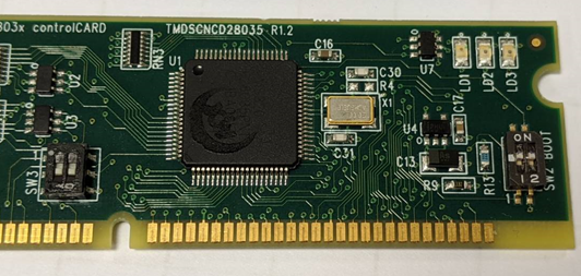
My experiment platform is TMS320C200 Experiment Kit(Piccolo F28035).
I was using ECAP module to implement a frequency counter.
The way I used to implement it is to capture 4 raising edge,

and used timestamp of cap4 to minus timestamp of cap1, than divided it by 3(as 1 cycle ticks).
Finially, divided 60M(system clock) by one cycle ticks to get frequency.

I used a wave generator to get a 20KHz square wave source and also used
oscilloscope to make sure the frequency of source is correct.
But my frequency measure result always lower than real frequency (about 400Hz ).

When I use CPU timer interrupt to make my own 20KHz square wave (toggle GPIO per 25 us), the measure seems to work better. (20013Hz).

But I am hoping to minimize the difference within 5Hz.

Is that ECAP setting wrong or system clock is not accurately enough?

  • PoWei,

    it seems like you have correctly configured the eCAP. I suspect that if you used a PWM, you would get a +/- 1 or 2 clock cycles of accuracy.

    The problem comes back to the inaccuracy of the internal oscillator, if you use an external crystal you should see better results.

    Please also note that if you follow the procedure in this appnote you should be able to get better accuracy.  

    Regards,
    Cody 

  • Hi

    I tried to use external crystal (20MHz external on ControlCard) by adding a function called XtalOscSel (in DSP2803x_SysCtrl.c file.)
    But my program seems to be frozen after adding this function.
    Is there any step I missed?
    (This following link which I was referenced)

    e2e.ti.com/.../754713

  • PoWei,

    Can you confirm if C30, C31, and X1 are populated?

    Regards,
    Cody 

  • Hi


    Yes, C30, C31, and X1 are populated.

    I simply added XtalOscSel function at top of my program.

    Is there any setting I missed which is related to this function?

    #include <DSP28x_Project.h>
    #include <stdio.h>
    #include <stdlib.h>
    
    #define SysClock 60000000
    
    __interrupt void cpu_timer0_isr(void);
    __interrupt void cpu_timer1_isr(void);
    __interrupt void ecap1_isr(void);
    
    void InitECapture();
    
    
    int counter=0;
    
    
    //------------------------MAIN START----------------------------//
    void main(void){
    //------------------------INITAIAL----------------------------//
        XtalOscSel();
        InitSysCtrl(); // init sys control(PLL watchdog peripheral clock)(DSP2803x_SysCtrl.c)
    //  InitGpio();    //Set the GPIO to it's default state.(DSP2803x_Gpio.c)
        DINT; //Clear all interrupts and initialize PIE vector table: Disable CPU interrupts
        InitPieCtrl(); //Initail PIE(Peripheral Interrupt Expansion) control reg
                       //all PIE interrupts disabled and flags are cleared.(DSP2803x_PieCtrl.c)
    
        // Disable CPU interrupts and clear all CPU interrupt flags:
        IER = 0x0000;
        IFR = 0x0000;
    
        // Init the PIE vector table with pointers to the shell Interrupt Service Routines (ISR).
        // This will populate the entire table, even if the interrupt
        // is not used in this example.  This is useful for debug purposes.
        // The shell ISR routines are found in DSP2803x_DefaultIsr.c.
        // This function is found in DSP2803x_PieVect.c.
        InitPieVectTable();
    
    
        // Interrupts that are used in this example are re-mapped to
        // ISR functions found within this file.
    
        EALLOW;  // This is needed to write to EALLOW protected registers
        //Those Interrupt name is in  DSP2803x_PieVect.h struct[PIE_VECT_TABLE]
        PieVectTable.TINT0 = &cpu_timer0_isr;
        PieVectTable.TINT1 = &cpu_timer1_isr;
        PieVectTable.ECAP1_INT = &ecap1_isr;
        EDIS;    // This is needed to disable write to EALLOW protected registers
    
    
        //Initialize the Device Peripheral
        InitCpuTimers();   //initialize the Cpu Timers (DSP2803x_CpuTimers.c)
        InitECapture();
    
    
        // Configure CPU-Timer 0 to interrupt every 500 milliseconds:
        // 60MHz CPU Freq, 50 millisecond Period (in uSeconds)
    
        ConfigCpuTimer(&CpuTimer0, 60, 500000);
        ConfigCpuTimer(&CpuTimer1, 60, 25);
    
        // Use write-only instruction to set TSS bit = 0
        CpuTimer0Regs.TCR.all = 0x4000;
        CpuTimer1Regs.TCR.all = 0x4000;
    
    
        //SetUp GPIO
        EALLOW;
        GpioCtrlRegs.GPAMUX1.bit.GPIO0 = 0;   //0 as GPIO, other as peripheral
        GpioCtrlRegs.GPADIR.bit.GPIO0 =1;     //0 as Input, 1 as Output
        GpioCtrlRegs.GPBMUX1.bit.GPIO34 = 0;  //0 as GPIO, other as peripheral
        GpioCtrlRegs.GPBDIR.bit.GPIO34 = 1;   //0 as Input, 1 as Output
        GpioCtrlRegs.GPAMUX2.bit.GPIO31 = 0;  //0 as GPIO, other as peripheral
        GpioCtrlRegs.GPADIR.bit.GPIO31 = 1;   //0 as Input, 1 as Output
    
        GpioCtrlRegs.GPAPUD.bit.GPIO19 = 0;     // Enable pull-up on GPIO19 (CAP1)
        GpioCtrlRegs.GPAQSEL2.bit.GPIO19 = 0;   // Synch to SYSCLKOUT GPIO19 (CAP1)
        GpioCtrlRegs.GPAMUX2.bit.GPIO19 = 3;    // Configure GPIO19 as CAP1
    
    
        EDIS;
    
        // Enable CPU INT
    
        IER |= M_INT1;  // INT1 which is connected to CPU-Timer 0
        IER |= M_INT13; // INT13 which is connected to CPU-Timer 1
        IER |= M_INT4;  // INT4 which is connected to ECAP1-4 INT
    
        // Enable interrupt in the PIE  number of Group and interrupt is in DSP2803x_PieVect.c struct[PIE_VECT_TABLE PieVectTableInit]
        PieCtrlRegs.PIEIER1.bit.INTx7 = 1; // Group 1 interrupt 7
        PieCtrlRegs.PIEIER4.bit.INTx1 = 1; // Group 4 interrupt 1
        // Enable global Interrupts and higher priority real-time debug events:
    
        EINT;       // Enable Global interrupt INTM
        ERTM;       // Enable Global realtime interrupt DBGM
    
    
    //---------------------------Loop----------------------------//
    
    
        for(;;){
    
        }
    }
    //------------------------MAIN END----------------------------//
    
    
    //-------------------------Function--------------------------//
    
    __interrupt void cpu_timer0_isr(void){  // Group 1 PIE Peripheral Vectors
        CpuTimer0.InterruptCount++;
        GpioDataRegs.GPBTOGGLE.bit.GPIO34 = 1; // Toggle GPIO34
        PieCtrlRegs.PIEACK.all = PIEACK_GROUP1; // Acknowledge this interrupt to receive more interrupts from group 1
    }
    
    
    __interrupt void cpu_timer1_isr(void){ //Non-Peripheral Interrupts
        CpuTimer1.InterruptCount++;
        GpioDataRegs.GPATOGGLE.bit.GPIO31 = 1;
        // no need to Acknowledge this interrupt to receive more interrupts from group 1
    }
    
    
    int ecap1_counter =0;
    int x=0;
    Uint32 cap1=0,cap2=0,cap3=0,cap4=0,InterCounter1=0,InterCounter2=0,InterCounter3=0;
    float Freq=0;
    
    __interrupt void ecap1_isr(void){
            x = (++ecap1_counter)/100;
            if(x==1){
                x=0;
                ecap1_counter=0;
                cap1=ECap1Regs.CAP1;
                cap2=ECap1Regs.CAP2;
                cap3=ECap1Regs.CAP3;
                cap4=ECap1Regs.CAP4;
                InterCounter1=(cap4-cap1);
                //InterCounter2=(cap4-cap2);
                InterCounter1=(InterCounter1)/3;
                Freq=(float)(SysClock/InterCounter1);  // Freq=1/InterTime & InterTime=(InterCounter*(1/clock))
                GpioDataRegs.GPATOGGLE.bit.GPIO0=1;
            }
            ECap1Regs.ECCLR.bit.CEVT4 = 1;
            ECap1Regs.ECCLR.bit.INT = 1;
            ECap1Regs.ECCTL2.bit.REARM = 1;
            ECap1Regs.ECCTL1.bit.CAPLDEN = 1;
            PieCtrlRegs.PIEACK.all = PIEACK_GROUP4; // Acknowledge this interrupt to receive more interrupts from group 4
    }
    
    void InitECapture(){
    
       ECap1Regs.ECEINT.all = 0x0000;        // Disable all capture interrupts
       ECap1Regs.ECCLR.all = 0xFFFF;         // Clear all CAP interrupt flags
       ECap1Regs.ECCTL1.bit.CAPLDEN = 0;     // Disable CAP1-CAP4 register loads
       ECap1Regs.ECCTL2.bit.TSCTRSTOP = 0;   // Make sure the counter is stopped
    
       // Configure peripheral registers
       ECap1Regs.ECCTL2.bit.CONT_ONESHT = 1;  // One-shot
       ECap1Regs.ECCTL2.bit.STOP_WRAP = 3;    // Stop at 4 events
       ECap1Regs.ECCTL2.bit.SWSYNC = 1;
       ECap1Regs.ECCTL1.bit.CAP1POL = 0;      // Falling edge
       ECap1Regs.ECCTL1.bit.CAP2POL = 0;      // Rising edge
       ECap1Regs.ECCTL1.bit.CAP3POL = 0;      // Falling edge
       ECap1Regs.ECCTL1.bit.CAP4POL = 0;      // Rising edge
       ECap1Regs.ECCTL1.bit.CTRRST1 = 0;      // Difference operation
       ECap1Regs.ECCTL1.bit.CTRRST2 = 0;      // Difference operation
       ECap1Regs.ECCTL1.bit.CTRRST3 = 0;      // Difference operation
       ECap1Regs.ECCTL1.bit.CTRRST4 = 1;      // Difference operation
       ECap1Regs.ECCTL2.bit.SYNCI_EN = 1;     // Enable sync in
       ECap1Regs.ECCTL2.bit.SYNCO_SEL = 0;    // Pass through
       ECap1Regs.ECCTL1.bit.CAPLDEN = 1;      // Enable capture units
    
       ECap1Regs.ECCTL2.bit.CAP_APWM = 0;
       ECap1Regs.ECCTL2.bit.TSCTRSTOP = 1;    // Start Counter
       ECap1Regs.ECCTL2.bit.REARM = 1;        // arm one-shot
       ECap1Regs.ECCTL1.bit.CAPLDEN = 1;      // Enable CAP1-CAP4 register loads
       ECap1Regs.ECEINT.bit.CEVT4 = 1;        // 4 events = interrupt
       GpioDataRegs.GPASET.bit.GPIO0=1;
    }
    

  • PoWei,

    please look at "1.3.2.3.1 Switching the Input Clock Source" inside of the TRM. It gives a basic guide of how to switch the clock source.

    I did not see an example code that did this, if i find one i will send it your way.

    Finally please move "XtalOscSel (void)" in side of the "InitSysCtrl();" function. Try replacing line 101.

    Regards,
    Cody 

  • Are you still having issues with this? This thread will be closing soon.

    Thanks,
    Cody 


  • Thanks for the help