This thread has been locked.

If you have a related question, please click the "Ask a related question" button in the top right corner. The newly created question will be automatically linked to this question.

CCS/TMDSHVRESLLCKIT: TMDSHVRESLLCKIT

Part Number: TMDSHVRESLLCKIT

Tool/software: Code Composer Studio

Hi all:

I'm reading the source code:D:\ti\controlSUITE\development_kits\TMDSHVRESLLCKIT_v1.0\HVLLC

I got a problem at build 3: when does the SR turn off?

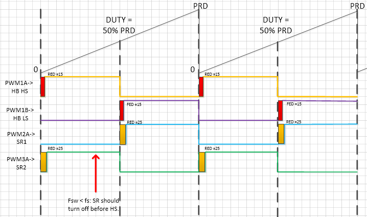
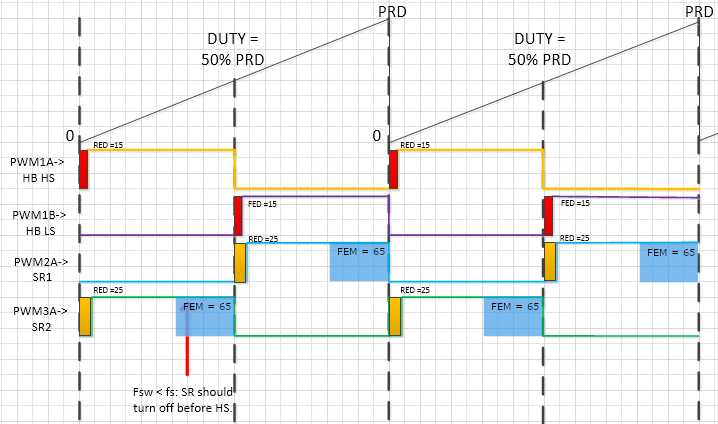
1) The SR PWM3A ON/OFF is initialized same to the HB HS PWM1A(ZERO = SET, COMPA = clear); the SR PWM2A is same to the HB HS PWM1B.

2) The Analog Comparators is initialized as below: 

// Configure ePWM Trip-Zone module
EPwm2Regs.TZCTL.bit.DCAEVT1 = TZ_FORCE_HI; // EPWM2A will go HIGH

EPwm3Regs.TZCTL.bit.DCAEVT1 = TZ_FORCE_HI; // EPWM3A will go HIGH

It means the SR will turn on when SR current is greater than the value of DACVAL.

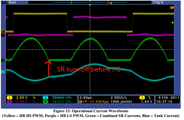
3)The SR PWM should be turn off before the HB HS PWM when fsw < fs.  This is show in the Figure 23 of "HVLLC-SWGuide.pdf"

Problem: Who turn off the SR PWM before the HB HS PWM when fsw < fs?

Looking forward to your reply. Thank you!

  • Hi Aiden,

    The rising and falling edge placement of the SR PWM waveforms is controlled with the deadband rising edge delay (RED) and falling edge delay (FED) registers in the PWM module.

    These deadband values are initialized in the main function (lines 421 and 424) and will control the placement of the SR waveform relative to the switching waveform:

    You can find the documentation for these driver modules in the DPLib.pdf document (C:\ti\controlSUITE\libs\app_libs\digital_power\f2802x_v3.2\Doc\DPLib.pdf).

    Does this answer your question?

    Best,

    Clayton Greenbaum

  • Hi Greenbaum,

    Thank you very much for your replay.

    I read the code again and did more homework. As you said "The rising and falling edge placement of the SR PWM waveforms is controlled with the deadband rising edge delay (RED) and falling edge delay (FED) registers in the PWM module." Do those PWM work as show below?

    SR PWM are turn off at the PRD or 50%PRD.

    My problem is still there "The SR PWM should be turn off before the HB HS PWM when fsw < fs(fs is the LLC resonance  frequency)."  

    Maybe where the red arrow is. This is also show in the Figure23 of "HVLLC-SWGuide.pdf"

    Problem: Who turn off the SR PWM before the HB HS PWM when fsw < fs?

    Look forward to your reply!

  • Hi Aiden,

    The diagram you drew is missing the falling edge shift (or falling edge margin) for the SR signals. If you check the DPLib documentation you'll find these figures:

    The PWMDRV_LLC_1ch_UpCntDB and PWMDRV_LLC_1ch_UpCntDB_Compl macros actually subtract the value in the DBFED register from the value in either the CMPA or TBPRD registers to advance the falling edge of the SR signals. The documentation describes how this works. In particular, it explains why changing the TBPRD register doesn't affect the period for the SR signal and this is due to the fact that PWM 2 and 3 are configured in slave mode and get sync events from PWM 1. See the excerpt below.

    Adding the falling edge shift to your drawing looks like this:

    Now the question remains, how does the SR signal get turned off? The trip zone configuration you highlighted forces the SR signal on anytime the SR current is greater than the value of DACVAL.

    // Configure ePWM Trip-Zone module
    EPwm2Regs.TZCTL.bit.DCAEVT1 = TZ_FORCE_HI; // EPWM2A will go HIGH
    
    EPwm3Regs.TZCTL.bit.DCAEVT1 = TZ_FORCE_HI; // EPWM3A will go HIGH

    This means anywhere in the FEM region where the SR current is greater than DACVAL the PWM output will be forced high. When the current goes below DACVAL anywhere in the FEM region, the trip zone event will no longer force the output of the PWM and the signal can go low.

    Let me know if this explains it.