This thread has been locked.

If you have a related question, please click the "Ask a related question" button in the top right corner. The newly created question will be automatically linked to this question.

TMS320F280049C: output waveform is wrong with CLB tool

Part Number: TMS320F280049C
Other Parts Discussed in Thread: C2000WARE

Hi Team,

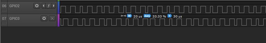
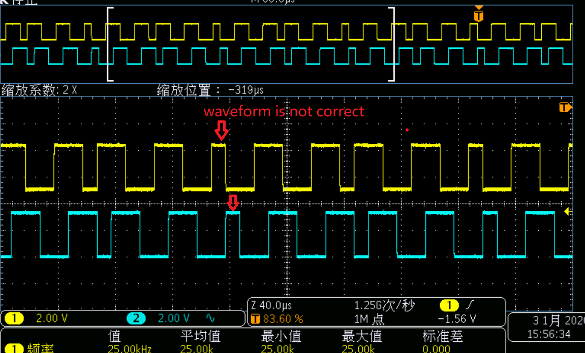
My customer are working on PTO function with CLB tool, now face a strange issue,  the CLB configuration is only for PWM waveform generation which duty cycle is fixed at 50%, the simulation waveform is correct, but sometimes the real output waveform is not correct as the below showed.

the code is modified from the example “clb_ex3_auxiliary_pwm”, the hardware is using F280049C Launchpad.

C:\ti\c2000\C2000Ware_2_00_00_03\driverlib\f28004x\examples\clb

Could you help reproduce this issue and find if anything wrong? Why the real output waveform is not the same as the simulation waveform? Thanks a lot.

  • Before we debug this and find the issue, 

    You are just trying to generate 50% duty PWM wave out of the CLB? You dont really need all the other features of the AUX PWM?

    Nima

  • Strong,

    I believe this is due to how the R0 and R1 values are being updated by the C28x.  The simulation does not know when the values are being updated, thus the problem is not seen.

    In the code you sent me, R0 and R1 are written to by the CPU at a high-rate in a while(1) loop.  This appears to be causing a conflict "some of the time". I suspect the CPU is trying to write a value to the register at the same time the HLC is trying to use the same register. 

    Please try moving the update to inside the interrupt from the HLC.  This is where the HLC update was in the original example provided by TI. 

    Regards

    Lori

  • Hi Lori,

    customer update R0/R1 in HLC interrupt, but still have this issue.

  • Strong,

    I saw a post that it worked, but now it didn't work?  Can you clarify?  Did the behavior change?

    -Lori

  • Strong,

    Here is what I observe:

    Update in while() loop:

        while(1)
        {
            asm(" NOP");
            CountR0 = Count;
            CountR1 = Count/2;
            CLB_writeInterface(CLB1_BASE, CLB_ADDR_HLC_R1, CountR1);
            CLB_writeInterface(CLB1_BASE, CLB_ADDR_HLC_R0, CountR0);
    
        }

    Update in HLC interrupt:

    __interrupt void clb1ISR(void)
    {
    #if 0
    .....   .......
    #endif
        CLB_writeInterface(CLB1_BASE, CLB_ADDR_HLC_R1, CountR1);   // line added here, commented out in while() loop
        CLB_writeInterface(CLB1_BASE, CLB_ADDR_HLC_R0, CountR0);   // line added here, commented out in while() loop
        CLB_clearInterruptTag(CLB1_BASE);
        Interrupt_clearACKGroup(INTERRUPT_ACK_GROUP5);
    }

  • Strong,

    There is a better approach described in the following application note:

     A method for updating the duty and period of a generated PWM waveform is described in section 7.  

    Regards

    Lori

  • Strong,

    I have confirmed with the CLB designers that the procedure in the application note must be followed when updating these registers during run-time. This procedure should be used for any scenario where some parameters of the CLB need to be modified while it is still running.

    The purpose of giving a path for C28x CPU to write to HLC registers (just like HLC instruction memory) is really meant for configuration-time and NOT for run-time.

    We will work to make this clear in the documentation and update any examples that violate this guidance.

    Regards

    Lori

  • Hi Lori,

    customer did the configuration following to the guide and the result better, but in same case of their application there will have possibility that in the C28 core update R0, R1 value, and at the same time CLB HLC update Match_value0, Match_value1 with R0, R1, then there will have an issue occur.

    If they add INTR 2 instruct in the CLB tool, then output waveform is wrong as below, Match_value0 was set the wrong value,

    Yellow is waveform generated by Match_value0, 

    Blue is waveform generated by Match_value1, 

    Purple is waveform generated by EPWM_ZERO_EVENT, which will trigger a CLB interrupt, and update R0, R1 value.

    but if they remove INTR 2 instruct in the CLB tool, then output waveform is correct as expected as below:

    question is how to handle the case that update R0,R1 in C28 code and update Match_value0,Match_value1 at the same time?

    why add INTR 2 instruct will cause the strange issue?

  • Strong,

    Strong ZHANG said:
    but in same case of their application there will have possibility that in the C28 core update R0, R1 value, and at the same time CLB HLC update Match_value0, Match_value1 with R0, R1, then there will have an issue occur.

    The C28x should not be updating the R0, R1 values directly while the system is running.  The C28x should update memory and then the HLC should pull the value from there into R0/R1.  Please confirm that R0 and R1 are not being updated directly by the C28x.  

    Regards

    Lori

  • Strong ZHANG said:
    how to handle the case that update R0,R1 in C28 code and update Match_value0,Match_value1 at the same time?

    Strong,

    I want to clarify 

    The procedure in the application note must be followed when updating these registers during run-time. This procedure must be used for any scenario where some parameters of the CLB need to be modified while it is still running.  The CLB was not designed to arbitrate between the C28x and CLB accesses.

    The purpose of giving a path for C28x CPU to write to HLC registers (just like HLC instruction memory) is meant for configuration-time only and NOT for run-time.

    Regards,

    -Lori

  • Hi Lori,

    Please confirm that R0 and R1 are not being updated directly by the C28x.  

    ----> R0, R1 are not updated by C28x, customer updated by PULL.

    I don't understand what run-time means, customer update R0, R1 in CLB interrupt which are triggered by PWM event and just run one time for one PWM period. customer just did a configuration to simulate the scenario that C28 update R0,R1 and HLC update Match_value0,Match_value1 at the same time.

    and find that have this issue. This scenario may occur in customer's application.

  • Hi Strong,

    Strong ZHANG said:
    I don't understand what run-time means

    • Initialization means the C28x is configuring the CLB.  The CLB is not running and not using its registers.  In this case the C28x can directly initialize R0/R1.
    • Run-time means that the system is running and the CLB is running.  The CLB is using its registers.  In this case the C28x must not directly update R0/R1.

    Strong ZHANG said:
    C28 update R0,R1 and HLC update Match_value0,Match_value1 at the same time

    If the application is using the pull method, then only the HLC updates R0/R1 and only the HLC updates the Match_value0/Match_value1.  Because the HLC is doing both updates there will not be a conflict.  The C28x only accesses the memory.

    Can you provide a timing diagram? Be very specific regarding whether the interrupt is to the C28x or a trigger within the CLB.  Also be specific regarding which component (C28x or HLC) is updating a register or memory location.

    Regards,

    -Lori