This thread has been locked.

If you have a related question, please click the "Ask a related question" button in the top right corner. The newly created question will be automatically linked to this question.

current input calculation on sine wave duty cyle

Part Number: TMS320F28035
Other Parts Discussed in Thread: CONTROLSUITE

Tool/software: Code Composer Studio

Hi,

I have C2000 experimental kits with TMS320F28035 to start evaluating my product. I am using SolarMicroInv_F2803x exmaple source for reference for my project.

I facing issue : Duty cycle is calculated wrong with grid input current. I want to understand how it works in duty cycle calculation.

below is the copy paste of calculation for duty cylce from example.

            cntlPI_BusInv.Ref   =Bus_Volt_notch.Out;
        cntlPI_BusInv.Fbk    =inv_bus_ref;
        CNTL_PI_IQ_MACRO(cntlPI_BusInv)
        inv_Iset=cntlPI_BusInv.Out;

        inv_ref_cur_inst = _IQ24mpy(inv_Iset, InvSine);
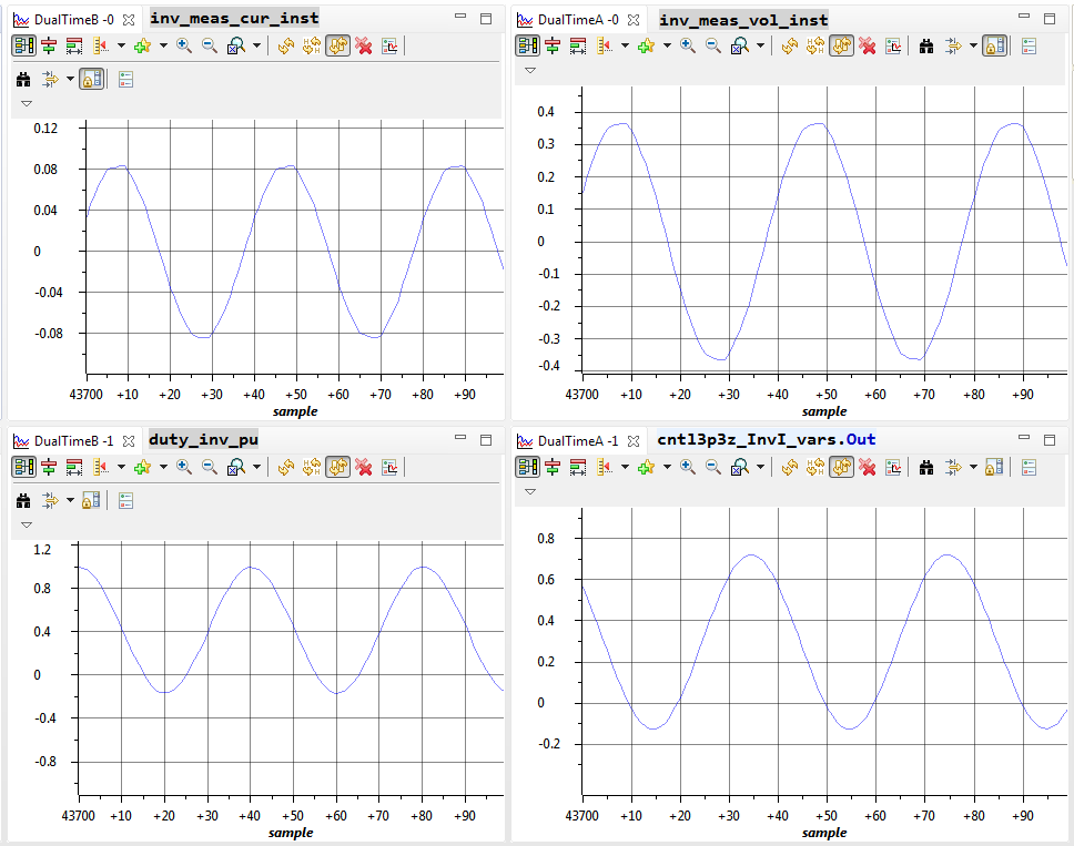
        cntl3p3z_InvI_vars.Ref=inv_ref_cur_inst;
        cntl3p3z_InvI_vars.Fdbk=inv_meas_cur_inst;
        CNTL_3P3Z_IQ_ASM(&cntl3p3z_InvI_coeff,&cntl3p3z_InvI_vars);
        duty_inv_pu=_IQ24div((cntl3p3z_InvI_vars.Out+inv_meas_vol_inst),vbus_meas_inst);
        duty_inv_pu= (duty_inv_pu>_IQ24(1.0))?_IQ24(1.0):duty_inv_pu;
        duty_inv_pu= (duty_inv_pu<_IQ24(-1.0))?_IQ24(-1.0):duty_inv_pu;


How inv_meas_cur_inst value is impacted on dutycycle?

it's good for me, if someone explain me how above calculation is works?

Thanks,

Jignesh Patel

  • Current controller output (cntl3p3z_Invl_vars.Out) is added to inverter output voltage (inv_meas_vol_inst) and then divide by the DC bus voltage (vbus_meas_inst) will result in the duty cycle output.

    This is called feedback linearization which is well known technique. Please study/review available papers on this topic. For yourFDBK_Linearization.pdf info a brief two page doc is attached. See the control block diagram on page 2.

    Shamim

  •  Thanks Shamim,

    I understand current is added in duty_inv_pu, but what is the functionality of the following equation:
            CNTL_3P3Z_IQ_ASM(&cntl3p3z_InvI_coeff,&cntl3p3z_InvI_vars);
                 
    Output "cntl3p3z_InvI_vars.Out" value is below zero levels. because of that duty_inv_pu has a wrong offset. so the result of this I am getting a duty cycle ~37 percentage.

    can you please explain what is the role of the above equation, why it's offset getting wrong?

    Initial setting of cntl3p3z_InvI_coeff is:
        cntl3p3z_InvI_coeff.Coeff_A1 = _IQ24(1.584);
        cntl3p3z_InvI_coeff.Coeff_A2 = _IQ24(-0.6978);
        cntl3p3z_InvI_coeff.Coeff_A3 = _IQ24(0.1137);
        cntl3p3z_InvI_coeff.Coeff_B0 = _IQ24(0.2866);
        cntl3p3z_InvI_coeff.Coeff_B1 = _IQ24(-0.3173);
        cntl3p3z_InvI_coeff.Coeff_B2 = _IQ24(0.3338);
        cntl3p3z_InvI_coeff.Coeff_B3 = _IQ24(-0.2616);

        cntl3p3z_InvI_coeff.Max = _IQ24(0.95);
        cntl3p3z_InvI_coeff.Min = _IQ24(-0.95);

    I have attached a snapshot of the graph for reference. Let me know you need any more information.

    Please guide me for a better understanding of this.

    Thanks,
    Jignesh Patel

  • what is the functionality of the following equation:
            CNTL_3P3Z_IQ_ASM(&cntl3p3z_InvI_coeff,&cntl3p3z_InvI_vars);

    This is where you call the 3p3z controller that controls the current to track the reference current. This function needs those parameters (inside the parenthesis) to execute the code and generate the control output.

  • I dont have idea of following equations becase that already in solar example :

            CNTL_3P3Z_IQ_ASM(&cntl3p3z_InvI_coeff,&cntl3p3z_InvI_vars);

    Thanks,

    Jignesh Patel

  • Install ControlSUITE  and then read the associated documentation available in the folder:

    C:\TI\controlSUITE\libs\app_libs\digital_power\f2803x_v3.5\Doc

    See Page 23 of the doc DPLib.pdf

    Shamim