This thread has been locked.

If you have a related question, please click the "Ask a related question" button in the top right corner. The newly created question will be automatically linked to this question.

CCS/TMS320F28035: When I open 'main.cfg' file In Explorer window of ILPFC project ,There's nothing in the interface,Why?

Part Number: TMS320F28035
Other Parts Discussed in Thread: SFRA

Tool/software: Code Composer Studio

      The following content is described in the document  “Digitally Controlled 2-Phase Interleaved Power Factor Correction(IL PFC) Converter Using C2000 Piccolo-A Microcontroller" 

       In the Project Explorer window on the left, click on the arrow sign to the left of ILPFC project. Your project window will look like the following in Figure 2.1.5:

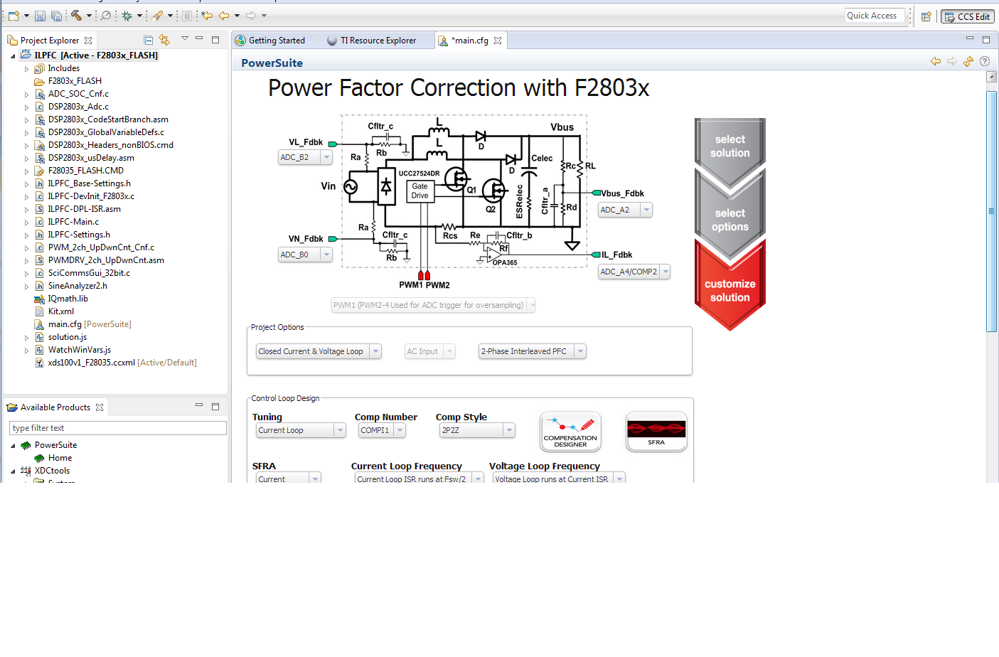
Figure 2.1.5. CCS Project Window

        Click on ‘main.cfg’ file if this is not open. This is the Solution Adaptor GUI for the IL PFC kit. The Solution Adaptor tool allows users to adapt existing code examples from TI on the digital ILPFC kit and configure them to run on their custom digital ILPFC board that uses the same PFC topology and similar C2000 resources. Explore the GUI from the ‘main.cfg’ file in order to get familiar with the different options it provides. As shown in Figure 2.1.5, this GUI displays the interleaved PFC topology used in TI IL PFC kit. It shows the PWM and ADC channels used in this design. The associated pulldown boxes allow you to change these PWM & ADC channels when you design your custom PFC board. The Solution Adaptor page also shows ‘Project Options’, ‘Control Loop Design’ options and ‘Power Stage Parameter’ entry section. The ‘Project Options’ shows three different pull down boxes that allow for customization of the PFC design. 

        But when I open 'main.cfg' file,The displayed interface is as follows. There's nothing in the interface. Why?


  • Hi,

    The reason you are seeing a blank screen is because the GUI Composer Runtime v1 Application is not installed in your version of CCS. You will need to install it via the CCS App Center. You can follow the steps detailed here: https://e2e.ti.com/support/tools/ccs/f/81/p/572039/2104783#2104783

    By the way what version of CCS are you using?

    Regards,

    Ozino

  •      The following content is described in the document  “Digitally Controlled 2-Phase Interleaved Power Factor Correction(IL PFC) Converter Using C2000 Piccolo-A Microcontroller"  .   

          Click on the ‘Compensation Designer’ tool. A snap shot of this tool is shown in Figure 2.1.6. This shows the frequency response of the PFC power stage (Plant), the loop (OL) and the digital compensator (Comp). The plot indicates the bandwidth, the gain margin and the phase margin of the loop. The tool also allows the user to select between the ‘Modelled’ plant and the measured plant based on ‘SFRA Data’ and then change the compensation parameters in frequency domain (gain,pole frequency, zero frequency). When the compensation design is complete this tool generates the digital controller coefficients (Comp Coeff) which is saved in the file ‘ILPFC_Base-Settings.h’ with the appropriate controller number (Comp Number). 

    Figure 2.1.6. Compensation Designer Tool

        But when  I change the compensation parameters  fz0, fz1 and fp1  in frequency domain , and click on the 'Save COMP' button in Figure 2.1.6 ,  the other coefficients (B0,B1,B2,B3,A1,A2 and A3)do not change,the digital controller coefficients (Comp Coeff) is not saved in the file ‘ILPFC_Base-Settings.h’ with the appropriate controller number (Comp Number).  I Click on the ‘Compensation Designer’ tool again, and all  the compensation parameters  fz0, fz1 and fp1  in frequency domain will be restored to the original data. Why?


  • Sorry, I know why. I didn't press  'enter' key.

  • Okay, glad to hear you figured it out.