This thread has been locked.

If you have a related question, please click the "Ask a related question" button in the top right corner. The newly created question will be automatically linked to this question.

CCS/TMS320F28388D: SDFM Example issue

Part Number: TMS320F28388D
Other Parts Discussed in Thread: AMC1305L25

Tool/software: Code Composer Studio

Hello

I have a question during the example operation.

example = fcl_f2838x_tmdxiddk_cpu1.project 

(use : tmdxiddk279d (Motor driver eval) , tms320f28388 control card (mcu eval) )

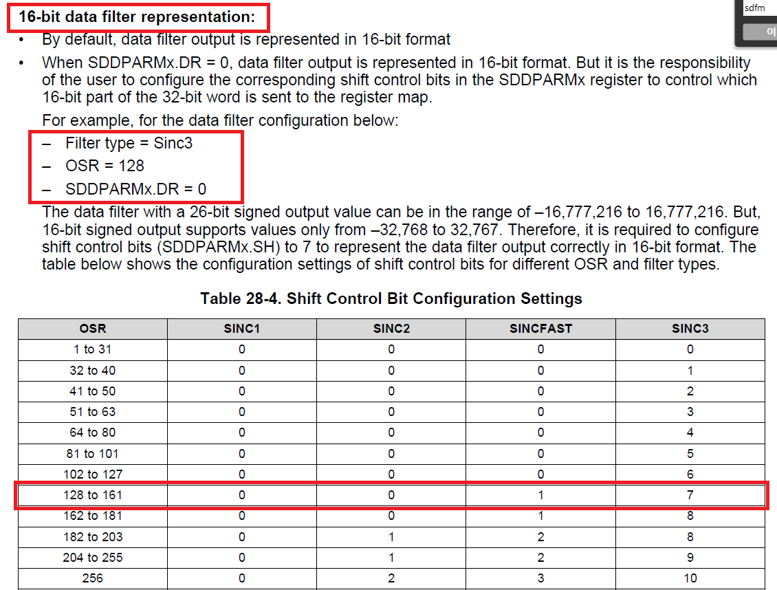
In the SDFM setting function filter settings.

OSR = 128 , sinc3 , shift bit = 7 

Referenced TRM., I know that.

However, the example uses 6 bits. (source code below.)

Why is it different?

// ******************************************************
// Sinc filter Module
// ******************************************************
// Configure Data filter module's filter type, OSR value and enable /
// disable data filter.
// 16 bit data representation is chosen for OSR 128 using Sinc3, from
// the table in the TRM.
// The max value represented for OSR 128 using sinc 3
// is +/-2097152 i.e. 2^21.
// To represent this in 16 bit format where the first bit is
// sign shift by 6 bits.
        
SDFM_enableFilter(SDFM1_BASE, (SDFM_FilterNumber)flt);
SDFM_setFilterType(SDFM1_BASE, (SDFM_FilterNumber)flt,
                           SDFM_FILTER_SINC_3);
SDFM_setFilterOverSamplingRatio(SDFM1_BASE, (SDFM_FilterNumber)flt,127);
//COSR = 127 +1  -> OSR = 128
SDFM_setOutputDataFormat(SDFM1_BASE, (SDFM_FilterNumber)flt,SDFM_DATA_FORMAT_16_BIT);
SDFM_setDataShiftValue(SDFM1_BASE, (SDFM_FilterNumber)flt,6);
//OSR = 128, SINC3 , 6? TRM = 7; 

  • Cho,

    If you can have the SD-modulator operate in specified linear full-scale range specified in the SD-modulator datasheet then you can use shift bit value 6 for OSR = 128.

    Regards,

    Manoj

  • Manoj, thank you for the answer.

    But I do not understand well.

    I looked at the data sheet.

    SINC3 = shift bit 7.

    why is shift bit 6?

    Thanks you.

  • Cho,

    Let me try to explain this with an example:

    When OSR = 128, a sinc3 filter will provide a digital output of 2097152 when SD-modulator applies a differential voltage greater than (or) equal to Vcliiping (Maximum differential voltage input range (AINP-AINN)). This Vclipping in defined in SD-modulator DS. For ex: In AMC1305L25, Table 7.10 Electrical characteristics defines Vclipping as 312.5mv. So, when the differential input applied exceeds (or) equals 312.5mv then SD-modulator is said be operating saturation.

    16-bit signed filter output can represent from -32768 (0x8000) to 0x32767 (0x7FFF)

    When SD-modulator is operating in +ve saturation: Differential input voltage >= +320mv, Sinc3 filter with OSR = 128 would give a filter output of  2097152, when you right shift by 6, it will give 32768. This number exceeds the maximum number 16-bit signed filter can represent. That is the reason why you right shift by 7. However, this problem will not arise when you ensure you will operate within linear full-scale range (specified in Table 7.10) = +/-250mv. In that case if you use right shift by 6 as the filter output cannot reach any value greater than 32767.

    In short, if you ensure to operate SD-modulator within the linear full-scale range, then you can right shift by 6 instead of 7 for OSR = 128 Sinc3 filter.

    Regards,

    Manoj

  • Manoj.

    Thank you!

    In short, OSR = 128 and Sinc3 Filter can shift ≤ 7.

    I think it can be changed flexibly according to the differential input voltage.

    regards,

    Cho.