This thread has been locked.

If you have a related question, please click the "Ask a related question" button in the top right corner. The newly created question will be automatically linked to this question.

CCS/LAUNCHXL-F28069M: Connecting EV3 to a Launchpad

Part Number: LAUNCHXL-F28069M
Other Parts Discussed in Thread: DRV8301

Tool/software: Code Composer Studio

Dear TI team, 

I want to connect EV3 Intelligent Brick (lego) to my F28069M launchpad, 

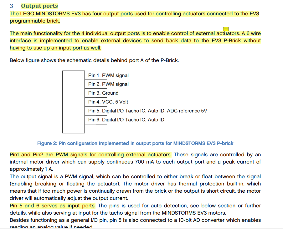
Here are the signals behind the output port of mindstorm I want to connect to,

 Is it possible to connect pin 1 & 2 (PMW signals), 5 & 6 (Digital I/O) to the launchpad ? (which pins are they). If you could point them out please. 

Thanks in advance, 

Best Regards, 

  • Hi Jinan,

    Are the signals on the EV3 Intelligent Brick 3.3V? The ADC reference saying 5V makes me think not.

    C2000 MCUs have 3.3V IOs and Analog inputs. You shouldn't connect to the EV3 Intelligent Brick directly if they are 5V signals.

    Best,

    Kevin

  • Dear Kevin, 

    1. I will be using the pin on EV3 with 5V  output, so I have to use op-amp circuitry, is there any hardware connection directory to how to implement it on launchpad f28069m development kit ? 

    2. I have several more questions 

    a- there are 16 analog inputs on the launchpad, (ADC) , so We connect the analog signal to one of these pin ? Where can I find simple and brief explanation to know the difference between each ?  (the technical reference is complicated and long)  .

    b- if I want to get the digital output from the launchpad back to the ev3,  which are the pins that are specific for reading digital data from the launchpad ? 

    c- What is the input and output  of ePWM pins ? ( I have read its part in the technical reference just want to make sure ). In the pdf it says ''The ePWM peripheral performs a digital to analog (DAC) function '' , but I couldnt see in the 8 submodels this function ! where can I see how it works in AD conversion ? 

    One more things about ePWM in the pdf it says 'This chapter guide is applicable for ePWM type 1. See the TMS320x28xx, 28xxx DSP Peripheral
    Reference Guide (SPRU566) for a list of all devices with an ePWM module of the same type, to determine
    the differences between the types, and for a list of device-specific differences within a type. '  However the pointed reference guide leads to the same technical reference ; I mean there is no explanation about the other types on ePWM !

    d-what is the relation between ADC and ePWM job ? 

    e- I am using a boostxl drv8301 evaluation module on the launchpad, how can I reach the headen pin ? (example ADCINA0(pin 27))

    It would be very helpful clearing out these points for me.

    Best Regards, 

    Jinan 

  • Jinan,

    Many of these questions about your EV3 system you will have to figure out on your own. We at TI are not familiar with the EV3 Intelligent Brick (lego) and don't know the type of signals it expects at its inputs/outputs.

    1. If the voltages you want to sample are higher than 3.3V, use a resistive voltage divider or op-amp circuit with fractional gain to get the input signal into range. (https://e2e.ti.com/support/microcontrollers/c2000/f/171/t/400731?Similar-microcontroller-to-F2802x-but-with-5V-ADC-)

    2. a) You can see Section 6 of the F2806x workshop, the TRM section will be the most in-depth documentation on the ADC. https://training.ti.com/c2000-f2806x-microcontroller-workshop?context=1137791-1137782

    b) Any C2000 GPIO can operate as a digital input or output (3.3V referenced). If you're asking which pins on the EV3, you'll need to find that on your own.

    c) The F2806x ePWM TRM section is the best and most in-depth document for this info, see the workshop for an introduction to the module. C2000 ePWM signal outputs will be 3.3V pulse trains.

    d) Not certain what you're asking here. The c2000 ePWM can be used to start an ADC conversion, i.e. set the sampling frequency

    e) If you have the DRV8301 board plugged into the LaunchPad you can reach the respective pins using the female connectors on the bottom of the board. That or wire-wrapping the signal to bring it out. Note that this signal is used for voltage sensing of phase C from the DRV8301 to the F2806x.

    Best,

    Kevin