


Part Number: LAUNCHXL-F28379D
Other Parts Discussed in Thread: TMS320F28379D
Hi All,
The i2c_ex1_loopback example loads and runs as expected, but I'm having a hard time understanding what's going on inside the code.
I've disabled loopback mode and inserted some I2C commands and data to populate a simple 2x16 char display.
Using the ISR to send data works until I issue a stop condition. As long as I don't use a stop condition (using the existing function "I2C_sendStopCondition(I2CA_BASE);"), all data is received by the display and all is well.
However, if I insert a stop condition, none of the code following it will stream over the I2C bus.
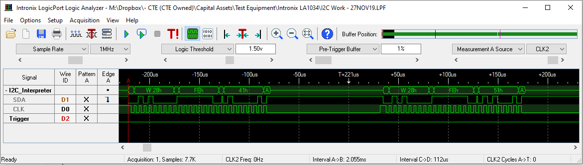
Here's the code without a stop condition until after all data has been sent: (display responds appropriately)
        strcpy(Line1, "  GMS-504DZ II  ");
                    // 1234567890123456
        strcpy(Line2, " FW Ver. 0.00.3 ");
                    // 1234567890123456

    I2C_setDataCount(I2CA_BASE, 2);         // Set number of bytes to transmit in the following I2C packets

        // Turn display on
    I2C_putData(I2CA_BASE, 0xfe);           // BYTE 1: Notify the I2C bus that a command is coming
        I2C_putData(I2CA_BASE, 0x41);       // BYTE 2: 0x41 is the command to turn on the display
        I2C_sendStartCondition(I2CA_BASE);  // Start sending the packet
//        I2C_sendStopCondition(I2CA_BASE);
        DEVICE_DELAY_US(125);               // Wait time specified by display manufacturer


        // Setup display to write 1st line
        I2C_putData(I2CA_BASE, 0xfe);           // BYTE 1: Notify the I2C bus that a command is coming
        I2C_putData(I2CA_BASE, 0x51);       // BYTE 2: 0x51 is the command to 'clear screen'
        I2C_sendStartCondition(I2CA_BASE);  // Start sending the packet
        DEVICE_DELAY_US(900);               // Wait time specified by display manufacturer

        I2C_putData(I2CA_BASE, 0xfe);           // Notify the I2C bus that a command is coming
        I2C_putData(I2CA_BASE, 0x4c);       // 0x4c is the command to turn the 'blinking cursor off'
        I2C_sendStartCondition(I2CA_BASE);  // Send the command message stated immediately above
        DEVICE_DELAY_US(125);               // Wait time specified by display manufacturer

        I2C_putData(I2CA_BASE, 0xfe);           // Notify the I2C bus that a command is coming
        I2C_putData(I2CA_BASE, 0x46);       // 0x46 is the command to send 'cursor home'
        I2C_sendStartCondition(I2CA_BASE);  // Start sending the packet
        DEVICE_DELAY_US(900);               // Wait time specified by display manufacturer

        I2C_setDataCount(I2CA_BASE, 3);         // Set number of bytes to transmit in the following I2C packets

        I2C_putData(I2CA_BASE, 0xfe);           // Notify the I2C bus that a command is coming
        I2C_putData(I2CA_BASE, 0x45);       // 0x45 is the command to 'set cursor'
        I2C_putData(I2CA_BASE, 0x00);       // 0x00 sets the cursor to 'Line 1, position 1'
        I2C_sendStartCondition(I2CA_BASE);  // Start sending the packet
        DEVICE_DELAY_US(125);               // Wait time specified by display manufacturer

        I2C_setDataCount(I2CA_BASE, 1);         // Set number of bytes to transmit in the following I2C packets

        // Send 1st line characters
        for(i = 0; i < 16; i++) {
            I2C_putData(I2CA_BASE, (uint16_t)Line1[i]);   // Send character to display
            I2C_sendStartCondition(I2CA_BASE);  // Send the character stated immediately above
            DEVICE_DELAY_US(100);               // Wait time specified by display manufacturer
        }

        I2C_setDataCount(I2CA_BASE, 3);         // Set number of bytes to transmit in the following I2C packets

        I2C_putData(I2CA_BASE, 0xfe);           // Notify the I2C bus that a command is coming
        I2C_putData(I2CA_BASE, 0x45);       // 0x45 is the command to 'set cursor'
        I2C_putData(I2CA_BASE, 0x40);       // 0x00 sets the cursor to 'Line 2, position 1'
        I2C_sendStartCondition(I2CA_BASE);  // Start sending the packet
        DEVICE_DELAY_US(125);               // Wait time specified by display manufacturer

        I2C_setDataCount(I2CA_BASE, 1);         // Set number of bytes to transmit in the following I2C packets

        // Send 2nd line characters
        for(i = 0; i < 16; i++) {
            I2C_putData(I2CA_BASE, Line2[i]);   // Send character to display
            I2C_sendStartCondition(I2CA_BASE);  // Send the character stated immediately above
            DEVICE_DELAY_US(100);               // Wait time specified by display manufacturer
        }

        I2C_sendStopCondition(I2CA_BASE);

        //
        // Clear interrupt flag
        //
        I2C_clearInterruptStatus(I2CA_BASE, I2C_INT_TXFF);
    }

    //
    // Issue ACK
    //
    Interrupt_clearACKGroup(INTERRUPT_ACK_GROUP8);
Here's what the above code produces: (all commands and data appear as expected and 2x16 display shows message correctly)
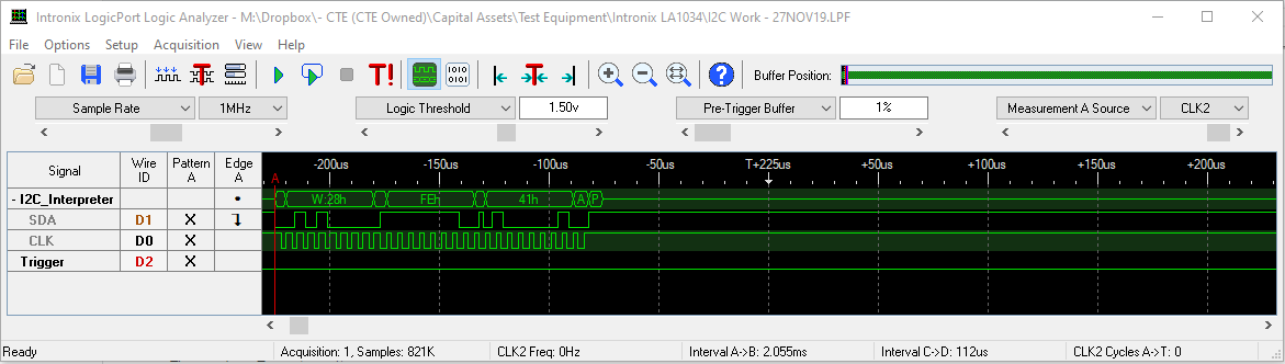
Here's the code with one instance of a stop condition after the first packet has been sent: (same as above, but stop condition function uncommented)
        strcpy(Line1, "  GMS-504DZ II  ");
                    // 1234567890123456
        strcpy(Line2, " FW Ver. 0.00.3 ");
                    // 1234567890123456

    I2C_setDataCount(I2CA_BASE, 2);         // Set number of bytes to transmit in the following I2C packets

        // Turn display on
    I2C_putData(I2CA_BASE, 0xfe);           // BYTE 1: Notify the I2C bus that a command is coming
        I2C_putData(I2CA_BASE, 0x41);       // BYTE 2: 0x41 is the command to turn on the display
        I2C_sendStartCondition(I2CA_BASE);  // Start sending the packet
        I2C_sendStopCondition(I2CA_BASE);
        DEVICE_DELAY_US(125);               // Wait time specified by display manufacturer


        // Setup display to write 1st line
        I2C_putData(I2CA_BASE, 0xfe);           // BYTE 1: Notify the I2C bus that a command is coming
        I2C_putData(I2CA_BASE, 0x51);       // BYTE 2: 0x51 is the command to 'clear screen'
        I2C_sendStartCondition(I2CA_BASE);  // Start sending the packet
        DEVICE_DELAY_US(900);               // Wait time specified by display manufacturer

        I2C_putData(I2CA_BASE, 0xfe);           // Notify the I2C bus that a command is coming
        I2C_putData(I2CA_BASE, 0x4c);       // 0x4c is the command to turn the 'blinking cursor off'
        I2C_sendStartCondition(I2CA_BASE);  // Send the command message stated immediately above
        DEVICE_DELAY_US(125);               // Wait time specified by display manufacturer

        I2C_putData(I2CA_BASE, 0xfe);           // Notify the I2C bus that a command is coming
        I2C_putData(I2CA_BASE, 0x46);       // 0x46 is the command to send 'cursor home'
        I2C_sendStartCondition(I2CA_BASE);  // Start sending the packet
        DEVICE_DELAY_US(900);               // Wait time specified by display manufacturer

        I2C_setDataCount(I2CA_BASE, 3);         // Set number of bytes to transmit in the following I2C packets

        I2C_putData(I2CA_BASE, 0xfe);           // Notify the I2C bus that a command is coming
        I2C_putData(I2CA_BASE, 0x45);       // 0x45 is the command to 'set cursor'
        I2C_putData(I2CA_BASE, 0x00);       // 0x00 sets the cursor to 'Line 1, position 1'
        I2C_sendStartCondition(I2CA_BASE);  // Start sending the packet
        DEVICE_DELAY_US(125);               // Wait time specified by display manufacturer

        I2C_setDataCount(I2CA_BASE, 1);         // Set number of bytes to transmit in the following I2C packets

        // Send 1st line characters
        for(i = 0; i < 16; i++) {
            I2C_putData(I2CA_BASE, (uint16_t)Line1[i]);   // Send character to display
            I2C_sendStartCondition(I2CA_BASE);  // Send the character stated immediately above
            DEVICE_DELAY_US(100);               // Wait time specified by display manufacturer
        }

        I2C_setDataCount(I2CA_BASE, 3);         // Set number of bytes to transmit in the following I2C packets

        I2C_putData(I2CA_BASE, 0xfe);           // Notify the I2C bus that a command is coming
        I2C_putData(I2CA_BASE, 0x45);       // 0x45 is the command to 'set cursor'
        I2C_putData(I2CA_BASE, 0x40);       // 0x00 sets the cursor to 'Line 2, position 1'
        I2C_sendStartCondition(I2CA_BASE);  // Start sending the packet
        DEVICE_DELAY_US(125);               // Wait time specified by display manufacturer

        I2C_setDataCount(I2CA_BASE, 1);         // Set number of bytes to transmit in the following I2C packets

        // Send 2nd line characters
        for(i = 0; i < 16; i++) {
            I2C_putData(I2CA_BASE, Line2[i]);   // Send character to display
            I2C_sendStartCondition(I2CA_BASE);  // Send the character stated immediately above
            DEVICE_DELAY_US(100);               // Wait time specified by display manufacturer
        }

        I2C_sendStopCondition(I2CA_BASE);

        //
        // Clear interrupt flag
        //
        I2C_clearInterruptStatus(I2CA_BASE, I2C_INT_TXFF);
    }

    //
    // Issue ACK
    //
    Interrupt_clearACKGroup(INTERRUPT_ACK_GROUP8);
Here's what happens with a stop condition: (no data is sent over I2C bus after the stop)
If I look at the registers just before the start condition function is called, after the stop condition was previously called, the registers look like this:

The MST register is '0', so I suspect nothing else will be sent until it's back in master mode. But, why did MST change to '0'? What am I missing? Do I need to reconfigure the I2C registers after every stop condition?
I've read the TMS320F28379D documentation (spruhm8i.pdf) several times, but I don't see what I'm doing wrong.
Any help is greatly appreciated.
Thanks,
robin
