This thread has been locked.

If you have a related question, please click the "Ask a related question" button in the top right corner. The newly created question will be automatically linked to this question.

LAUNCHXL-F28379D: SPI transfer data between F28379D-LAUNCHXL and CC3220SF-LAUNCHXL

Part Number: LAUNCHXL-F28379D
Other Parts Discussed in Thread: C2000WARE, CC3220SF-LAUNCHXL, CC3220SF, TMS320F28379D

I'm trying to figure out how to program the data transfer. The given example in the resource explorer is not getting me to move forward.

Kindly help me with some resources or other similar examples to help me understand on how to program them.

Thank you.

Varunkumar

  • Varun,

     SPI example code provided in C2000Ware should definitely help you get started. Did you try to get the running the example code and understand how SPI is working?

    We don't have any other generic SPI example code which we can share with you. If you have a specific question, I should be able to help you.

    Regards,

    Manoj

  • I ran the example code but I'm not able to figure out the result and also understand the operation. Basically I'm struggling to write the code. I don't understand how to learn to code in CCS. I would really appreciate some help please?

    Thanks.

    Regards

    Varun 

  • Varun,

    If you're getting started with F28379D, I would suggest you to make use online worshop training materials which included lab exercises and example projects. It gives a very good overview of various features on this device and its peripherals with example code.

    On-Line Workshop

    Multi-day On-Line Workshop

    Once you are through the workshop material, you should be in a position to perform the below steps to work with example code.

    Step1:Understand the below SPI example code and observe the SPI signals.

    Use the below project and modify the the SPIA GPIOs used as shown below. The compile the code and run the code

    Project: <C2000Ware>\device_support\f2837xd\examples\cpu1\spi_loopback\cpu01

    • Modify InitSpiaGpio() function  available in F2837xD_Spi.c to below GPIO shown below

    • When you run the above code, I would suggest you to monitor the above GPIO signals in launchpad using SPI protocol analyzer. It will show what is going on SPI bus.

    This example code configure SPIA as Master and runs standalone as internal loop back is enabled. You don't need to make any external hardware connection.

    Step2: Once you completely understand this code, you can modify this code to communicate with CC3220SF-LAUNCHXL.

    • If you are planning to connect F28379D-LAUNCHXL and CC3220SF-LAUNCHXL by snapping the board together you need to modify the the SPIA GPIOs used as shown below. In this case you have use GPIO123 as output pin and use it as a SPIASTE pin as snapping the boards connects F28379D.GPIO123 and CC3220SF.GPIO17 (if any questions, please check the schematics)
    • Need to disable  internal loopback mode ( SpiaRegs.SPICCR.bit.SPILBK = 0;)
    • Then you need to make sure CC3220SF.SPI is configured as slave using the GPIO14, 15, 16,17 of CC3220SF. Only if both the devices SPIs are configured correctly, you will be able to get them talk with each other.

    Hope this helps. Best of luck and welcome to C2000!!!

    Happy programming!

    Regards,

    Manoj

  • Hey Manoj!

    Thank you for your reply it was helpful to proceed with my project. Unfortunately I made an error while asking the question. I'm actually using

    F28379D control card and R4.1 control card docking station. I'm trying to achieve SPI communication between control card and CC3220sf - LaunchXL.

    The data to be transferred is the ADC value (continuously read) which is read by the CC3220sf (SLAVE) and then the value is to be received by F28379D Control card (MASTER). I configured everything and even the handshake process seems to work. I used an oscilloscope to debug the signals and change the code. Other than that I'm finding it difficult to debug the code.

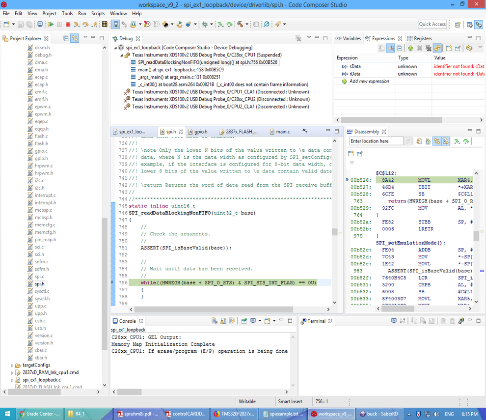
    I really tried my best but, I'm struggling to understand the coding part. The code gets stuck in a loop which is part of some header file or also sometimes It gives me some exception. I have added the code and screenshot of where it has halted for your reference.  I would really appreciate if you can help me with this so that I can proceed ahead.

    Thank you

    Varunkumar

    /*
     * Copyright (c) 2015-2019, Texas Instruments Incorporated
     * All rights reserved.
     *
     * Redistribution and use in source and binary forms, with or without
     * modification, are permitted provided that the following conditions
     * are met:
     *
     * *  Redistributions of source code must retain the above copyright
     *    notice, this list of conditions and the following disclaimer.
     *
     * *  Redistributions in binary form must reproduce the above copyright
     *    notice, this list of conditions and the following disclaimer in the
     *    documentation and/or other materials provided with the distribution.
     *
     * *  Neither the name of Texas Instruments Incorporated nor the names of
     *    its contributors may be used to endorse or promote products derived
     *    from this software without specific prior written permission.
     *
     * THIS SOFTWARE IS PROVIDED BY THE COPYRIGHT HOLDERS AND CONTRIBUTORS "AS IS"
     * AND ANY EXPRESS OR IMPLIED WARRANTIES, INCLUDING, BUT NOT LIMITED TO,
     * THE IMPLIED WARRANTIES OF MERCHANTABILITY AND FITNESS FOR A PARTICULAR
     * PURPOSE ARE DISCLAIMED. IN NO EVENT SHALL THE COPYRIGHT OWNER OR
     * CONTRIBUTORS BE LIABLE FOR ANY DIRECT, INDIRECT, INCIDENTAL, SPECIAL,
     * EXEMPLARY, OR CONSEQUENTIAL DAMAGES (INCLUDING, BUT NOT LIMITED TO,
     * PROCUREMENT OF SUBSTITUTE GOODS OR SERVICES; LOSS OF USE, DATA, OR PROFITS;
     * OR BUSINESS INTERRUPTION) HOWEVER CAUSED AND ON ANY THEORY OF LIABILITY,
     * WHETHER IN CONTRACT, STRICT LIABILITY, OR TORT (INCLUDING NEGLIGENCE OR
     * OTHERWISE) ARISING IN ANY WAY OUT OF THE USE OF THIS SOFTWARE,
     * EVEN IF ADVISED OF THE POSSIBILITY OF SUCH DAMAGE.
     */
    
     /*
       *  ======== spislave.c ========
       */
      #include <stddef.h>
      #include <stdint.h>
      #include <string.h>
    
      /* POSIX Header files */
      #include <pthread.h>
      #include <semaphore.h>
      #include <unistd.h>
    
      /* Driver Header files */
      #include <ti/drivers/GPIO.h>
      #include <ti/drivers/SPI.h>
      #include <ti/drivers/ADC.h>
      #include <ti/display/Display.h>
    
      /* Driver configuration */
      #include "ti_drivers_config.h"
    
      #define THREADSTACKSIZE (1024)
    
     // #define SPI_MSG_LENGTH  (30)
     // #define SLAVE_MSG       ("Hello from slave, msg#: ")
    
      #define MAX_LOOP        (10)
    
      static Display_Handle display;
    
      /* global variableS FOR GUI COMPOSER */
      uint16_t adcValue = 0;
      uint16_t threshold = 100;
      uint16_t alert = 0;
      uint32_t adcValue0MicroVolt;
      float adcValueVolt;
    
    
      uint16_t slaveRxBuffer;
      uint16_t slaveTxBuffer;
    
      /* Semaphore to block slave until transfer is complete */
      sem_t slaveSem;
    
      /*
       *  ======== transferCompleteFxn ========
       *  Callback function for SPI_transfer().
       */
      void transferCompleteFxn(SPI_Handle handle, SPI_Transaction *transaction)
      {
          sem_post(&slaveSem);
      }
    
    
      /*
         * ======== slaveThread ========
         *  Slave SPI sends a message to master while simultaneously receiving a
         *  message from the master.
         */
        void *slaveThread(void *arg0)
        {
            SPI_Handle      slaveSpi;
            SPI_Params      spiParams;
            SPI_Transaction transaction;
            //uint32_t        i;
            bool            transferOK;
            int32_t         status;
    
            /*
             * CONFIG_SPI_MASTER_READY & CONFIG_SPI_SLAVE_READY are GPIO pins connected
             * between the master & slave.  These pins are used to synchronize
             * the master & slave applications via a small 'handshake'.  The pins
             * are later used to synchronize transfers & ensure the master will not
             * start a transfer until the slave is ready.  These pins behave
             * differently between spimaster & spislave examples:
             *
             * spislave example:
             *     * CONFIG_SPI_MASTER_READY is configured as an input pin.  During the
             *       'handshake' this pin is read & a high value will indicate the
             *       master is ready to run the application.  Afterwards, the pin is
             *       read to determine if the master has already opened its SPI pins.
             *       The master will pull this pin low when it has opened its SPI.
             *
             *     * CONFIG_SPI_SLAVE_READY is configured as an output pin.  During the
             *       'handshake' this pin is changed from low to high output.  This
             *       notifies the master the slave is ready to run the application.
             *       Afterwards, the pin is used by the slave to notify the master it
             *       is ready for a transfer.  When ready for a transfer, this pin will
             *       be pulled low.
             *
             * Below we set CONFIG_SPI_MASTER_READY & CONFIG_SPI_SLAVE_READY initial
             * conditions for the 'handshake'.
             */
            GPIO_setConfig(CONFIG_SPI_SLAVE_READY, GPIO_CFG_OUTPUT | GPIO_CFG_OUT_LOW);
            GPIO_setConfig(CONFIG_SPI_MASTER_READY, GPIO_CFG_INPUT);
    
            /*
             * Handshake - Set CONFIG_SPI_SLAVE_READY high to indicate slave is ready
             * to run.  Wait for CONFIG_SPI_MASTER_READY to be high.
             */
            GPIO_write(CONFIG_SPI_SLAVE_READY, 0);
            while (GPIO_read(CONFIG_SPI_MASTER_READY) == 0) {}
    
            /*
             * Create synchronization semaphore; this semaphore will block the slave
             * until a transfer is complete.  The slave is configured in callback mode
             * to allow us to configure the SPI transfer & then notify the master the
             * slave is ready.  However, we must still wait for the current transfer
             * to be complete before setting up the next.  Thus, we wait on slaveSem;
             * once the transfer is complete the callback function will unblock the
             * slave.
             */
            status = sem_init(&slaveSem, 0, 0);
            if (status != 0) {
               Display_printf(display, 0, 0, "Error creating slaveSem\n");
    
                while(1);
            }
    
            /*
             * Wait until master SPI is open.  When the master is configuring SPI pins
             * the clock may toggle from low to high (or high to low depending on
             * polarity).  If using 3-pin SPI & the slave has been opened before the
             * master, clock transitions may cause the slave to shift bits out assuming
             * it is an actual transfer.  We can prevent this behavior by opening the
             * master first & then opening the slave.
             */
            while (GPIO_read(CONFIG_SPI_MASTER_READY)==0) {}
    
            /*
             * Open SPI as slave in callback mode; callback mode is used to allow us to
             * configure the transfer & then set CONFIG_SPI_SLAVE_READY high.
             */
            SPI_Params_init(&spiParams);
            spiParams.frameFormat = SPI_POL0_PHA1;
            spiParams.mode = SPI_SLAVE;
            spiParams.transferCallbackFxn = transferCompleteFxn;
            spiParams.transferMode = SPI_MODE_CALLBACK;
            slaveSpi = SPI_open(CONFIG_SPI_SLAVE, &spiParams);
            if (slaveSpi == NULL) {
                Display_printf(display, 0, 0, "Error initializing slave SPI\n");
                while (1);
            }
            else {
               Display_printf(display, 0, 0, "Slave SPI initialized\n");
            }
    
            /* Copy message to transmit buffer */
           // strncpy((char *) slaveTxBuffer, SLAVE_MSG, SPI_MSG_LENGTH);
            slaveTxBuffer = adcValue;
    
    
                /* Initialize slave SPI transaction structure */
               // slaveTxBuffer[sizeof(SLAVE_MSG) - 1] = (i % 10) + '0';
                memset((void *) slaveRxBuffer, 0, sizeof(adcValue));
                transaction.count = sizeof(adcValue);
                transaction.txBuf = (void *) slaveTxBuffer;
                transaction.rxBuf = (void *) slaveRxBuffer;
    
                /* Toggle on user LED, indicating a SPI transfer is in progress */
                GPIO_toggle(CONFIG_GPIO_LED_1);
    
                /*
                 * Setup SPI transfer; CONFIG_SPI_SLAVE_READY will be set to notify
                 * master the slave is ready.
                 */
                transferOK = SPI_transfer(slaveSpi, &transaction);
                if (transferOK) {
                    GPIO_write(CONFIG_SPI_SLAVE_READY, 1);
    
                    /* Wait until transfer has completed */
                    sem_wait(&slaveSem);
    
                    /*
                     * Drive CONFIG_SPI_SLAVE_READY high to indicate slave is not ready
                     * for another transfer yet.
                     */
                    GPIO_write(CONFIG_SPI_SLAVE_READY, 1);
    
    
                   Display_printf(display, 0, 0, "Slave received: %s", slaveRxBuffer);
                }
                else {
                    Display_printf(display, 0, 0, "Unsuccessful slave SPI transfer");
                }
    
    
            SPI_close(slaveSpi);
    
            /* Example complete - set pins to a known state */
            GPIO_setConfig(CONFIG_SPI_MASTER_READY, GPIO_CFG_OUTPUT | GPIO_CFG_OUT_LOW);
            GPIO_write(CONFIG_SPI_SLAVE_READY, 0);
    
            Display_printf(display, 0, 0, "\nDone");
    
            return (NULL);
        }
    
    
        void *threadFxn0(void *arg0)
        {
            /* Open ADC Driver */
            uint32_t time = 100000;  // update ~10/second
                  ADC_Handle adc;
                  ADC_Params params;
                  ADC_Params_init(&params);
                  adc = ADC_open(CONFIG_ADC_0, &params);
                  if (adc == NULL) {
                      // Error initializing ADC channel 0
                      while (1);
                  }
    
                  while (1) {
                      int_fast16_t res;
    
                      res = ADC_convert(adc, &adcValue);
                      if (res == ADC_STATUS_SUCCESS) {
                          adcValue0MicroVolt = ADC_convertRawToMicroVolts(adc, adcValue);
                          adcValueVolt = adcValue0MicroVolt*0.000001*998/422;
                                  Display_printf(display, 0, 0, "ADC0 raw result: %d\n", adcValue);
                                  Display_printf(display, 0, 0, "ADC0 convert result: %d uV\n",
                                      adcValue0MicroVolt);
                          if(adcValue >= threshold) {
                              GPIO_write(CONFIG_GPIO_LED_0, CONFIG_GPIO_LED_ON);
                              alert = 1;
                          } else{
                              GPIO_write(CONFIG_GPIO_LED_0, CONFIG_GPIO_LED_OFF);
                              alert = 0;
                          }
                      }
    
                      usleep(time);
                  }
    
              }
    
      /*
       *  ======== mainThread ========
       */
    
      void *mainThread(void *arg0)
      {
          /* ~10 loops/second */
    
          GPIO_write(CONFIG_SPI_SLAVE_READY, 0);
          /* Call driver init functions */
          GPIO_init();
          ADC_init();
          // I2C_init();
          SPI_init();
          // UART_init();
          // Watchdog_init();
    
                pthread_t           thread0, thread1;
                pthread_attr_t      attrs;
                struct sched_param  priParam;
                int                 retc;
                int                 detachState;
    
                /* Call driver init functions. */
                Display_init();
    
                /* Configure the LED pins */
                GPIO_setConfig(CONFIG_GPIO_LED_0, GPIO_CFG_OUT_STD | GPIO_CFG_OUT_LOW);
                GPIO_setConfig(CONFIG_GPIO_LED_1, GPIO_CFG_OUT_STD | GPIO_CFG_OUT_LOW);
    
                // Open the display for output
                display = Display_open(Display_Type_UART, NULL);
                if (display == NULL) {
                    /* Failed to open display driver */
                    while (1);
                }
    
                /* Turn on user LED */
                GPIO_write(CONFIG_GPIO_LED_0, CONFIG_GPIO_LED_ON);
    
                Display_printf(display, 0, 0, "Starting the SPI slave example");
                Display_printf(display, 0, 0, "This example requires external wires to be "
                    "connected to the header pins. Please see the Board.html for details.\n");
    
                /* Create application thread */
                pthread_attr_init(&attrs);
    
                detachState = PTHREAD_CREATE_DETACHED;
                /* Set priority and stack size attributes */
                retc = pthread_attr_setdetachstate(&attrs, detachState);
                if (retc != 0) {
                    /* pthread_attr_setdetachstate() failed */
                    while (1);
                }
    
                retc |= pthread_attr_setstacksize(&attrs, THREADSTACKSIZE);
                if (retc != 0) {
                    /* pthread_attr_setstacksize() failed */
                    while (1);
                }
    
                /* Create slave thread */
                priParam.sched_priority = 1;
                pthread_attr_setschedparam(&attrs, &priParam);
    
                retc = pthread_create(&thread0, &attrs, threadFxn0, NULL);
                    if (retc != 0) {
                        /* pthread_create() failed */
                        while (1);
                    }
    
                retc = pthread_create(&thread1, &attrs, slaveThread, NULL);
                if (retc != 0) {
                    /* pthread_create() failed */
                    while (1);
                }
                return (NULL);
      }


    F28379D spi code
    //#############################################################################
    //
    // FILE:   spi_ex1_loopback.c
    //
    // TITLE:  SPI Digital Loopback
    //
    //! \addtogroup driver_example_list
    //! <h1>SPI Digital Loopback</h1>
    //!
    //! This program uses the internal loopback test mode of the SPI module. This
    //! is a very basic loopback that does not use the FIFOs or interrupts. A
    //! stream of data is sent and then compared to the received stream.
    //!
    //! The sent data looks like this: \n
    //!  0000 0001 0002 0003 0004 0005 0006 0007 .... FFFE FFFF 0000
    //!
    //! This pattern is repeated forever.
    //!
    //! \b External \b Connections \n
    //!  - None
    //!
    //! \b Watch \b Variables \n
    //!  - \b sData - Data to send
    //!  - \b rData - Received data
    //!
    //
    //#############################################################################
    // $TI Release: F2837xD Support Library v3.08.00.00 $
    // $Release Date: Mon Dec 23 17:32:30 IST 2019 $
    // $Copyright:
    // Copyright (C) 2013-2019 Texas Instruments Incorporated - http://www.ti.com/
    //
    // Redistribution and use in source and binary forms, with or without 
    // modification, are permitted provided that the following conditions 
    // are met:
    // 
    //   Redistributions of source code must retain the above copyright 
    //   notice, this list of conditions and the following disclaimer.
    // 
    //   Redistributions in binary form must reproduce the above copyright
    //   notice, this list of conditions and the following disclaimer in the 
    //   documentation and/or other materials provided with the   
    //   distribution.
    // 
    //   Neither the name of Texas Instruments Incorporated nor the names of
    //   its contributors may be used to endorse or promote products derived
    //   from this software without specific prior written permission.
    // 
    // THIS SOFTWARE IS PROVIDED BY THE COPYRIGHT HOLDERS AND CONTRIBUTORS 
    // "AS IS" AND ANY EXPRESS OR IMPLIED WARRANTIES, INCLUDING, BUT NOT 
    // LIMITED TO, THE IMPLIED WARRANTIES OF MERCHANTABILITY AND FITNESS FOR
    // A PARTICULAR PURPOSE ARE DISCLAIMED. IN NO EVENT SHALL THE COPYRIGHT 
    // OWNER OR CONTRIBUTORS BE LIABLE FOR ANY DIRECT, INDIRECT, INCIDENTAL, 
    // SPECIAL, EXEMPLARY, OR CONSEQUENTIAL DAMAGES (INCLUDING, BUT NOT 
    // LIMITED TO, PROCUREMENT OF SUBSTITUTE GOODS OR SERVICES; LOSS OF USE,
    // DATA, OR PROFITS; OR BUSINESS INTERRUPTION) HOWEVER CAUSED AND ON ANY
    // THEORY OF LIABILITY, WHETHER IN CONTRACT, STRICT LIABILITY, OR TORT 
    // (INCLUDING NEGLIGENCE OR OTHERWISE) ARISING IN ANY WAY OUT OF THE USE 
    // OF THIS SOFTWARE, EVEN IF ADVISED OF THE POSSIBILITY OF SUCH DAMAGE.
    // $
    //#############################################################################
    
    //
    // Included Files
    //
    #include "driverlib.h"
    #include "device.h"
    
    //
    // Number of times the loop runs (Increase it if needed)
    //
    uint16_t LOOP_COUNT = 100;
    
    //
    // Function Prototypes
    //
    void initSPI(void);
    
    //
    // Main
    //
    void main(void)
    {
        uint16_t sData = 0;                  // Send data
        uint16_t rData = 0;                  // Receive data
    
        //
        // Initialize device clock and peripherals
        //
        Device_init();
    
        //
        // Disable pin locks and enable internal pullups.
        //
        Device_initGPIO();
    
    
            GPIO_setPadConfig(40, GPIO_PIN_TYPE_PULLUP);     // Enable pullup on GPIO13
                GPIO_setPinConfig(GPIO_40_GPIO40);               // GPIO13 = GPIO13
                GPIO_setDirectionMode(40, GPIO_DIR_MODE_IN);     // GPIO13 = input


                GPIO_setPadConfig(41, GPIO_PIN_TYPE_PULLUP);    // Enable pullup on GPIO11
                  //GPIO_writePin(11, 0);                           // Load output latch
                    GPIO_setPinConfig(GPIO_41_GPIO41);              // GPIO11 = GPIO11
                    GPIO_setDirectionMode(41, GPIO_DIR_MODE_OUT);   // GPIO11 = output
    
                    GPIO_writePin(41, 0);  // Master ready to receive
                    while (GPIO_readPin(40)==1){}
                    GPIO_writePin(41, 1);
    
                GPIO_setPadConfig(16, GPIO_PIN_TYPE_PULLUP); // Pullup on GPIO16 (SPISIMOA)
                GPIO_setPadConfig(17, GPIO_PIN_TYPE_PULLUP); // Pullup on GPIO17 (SPIS0MIA)
                GPIO_setPadConfig(18, GPIO_PIN_TYPE_PULLUP); // Pullup on GPIO18 (SPICLKA)
                GPIO_setPadConfig(19, GPIO_PIN_TYPE_PULLUP); // Pullup on GPIO19 (SPISTEA)
                GPIO_setQualificationMode(16, GPIO_QUAL_ASYNC); // asynch input
                GPIO_setQualificationMode(17, GPIO_QUAL_ASYNC); // asynch input
                GPIO_setQualificationMode(18, GPIO_QUAL_ASYNC); // asynch input
                GPIO_setQualificationMode(19, GPIO_QUAL_ASYNC); // asynch input
                GPIO_setPinConfig(GPIO_16_SPISIMOA);            // GPIO16 = SPISIMOA
                GPIO_setPinConfig(GPIO_17_SPISOMIA);            // GPIO17 = SPIS0MIA
                GPIO_setPinConfig(GPIO_18_SPICLKA);             // GPIO18 = SPICLKA
                GPIO_setPinConfig(GPIO_19_SPISTEA);             // GPIO19 = SPISTEA
    
    
        //
        // Initialize PIE and clear PIE registers. Disables CPU interrupts.
        //
        Interrupt_initModule();
    
        //
        // Initialize the PIE vector table with pointers to the shell Interrupt
        // Service Routines (ISR).
        //
        Interrupt_initVectorTable();
    
        //
        // Set up SPI, initializing it for FIFO mode
        //
        initSPI();
        GPIO_writePin(41, 1);
        //
        // Enable Global Interrupt (INTM) and realtime interrupt (DBGM)
        //
        EINT;
        ERTM;
    
        //
        // Loop forever. Suspend or place breakpoints to observe the buffers.
        //
        while(1)
        {
            // Transmit data
            SPI_writeDataNonBlocking(SPIA_BASE, sData);
    
            // Block until data is received and then return it
            rData = SPI_readDataBlockingNonFIFO(SPIA_BASE);
    
            // Check received data against sent data
          /*  if(rData != sData)
            {
                // Something went wrong. rData doesn't contain expected data.
                Example_Fail = 1;
                ESTOP0;
            }
                    */
            sData++;
    
            Example_PassCount++;
        }
    
    
    }
    
    //
    // Function to configure SPI A in FIFO mode.
    //
    void initSPI()
    {
        //
        // Must put SPI into reset before configuring it
        //
        SPI_disableModule(SPIA_BASE);
    
        //
        // SPI configuration. Use a 1MHz SPICLK and 16-bit word size.
        //
        SPI_setConfig(SPIA_BASE, DEVICE_LSPCLK_FREQ, SPI_PROT_POL0PHA0,
                      SPI_MODE_MASTER, 1000000, 16);
        //SPI_enableLoopback(SPIA_BASE);
        SPI_setEmulationMode(SPIA_BASE, SPI_EMULATION_STOP_AFTER_TRANSMIT);
    
        //
        // Configuration complete. Enable the module.
        //
        SPI_enableModule(SPIA_BASE);
    
    
    }


  • If your code is stuck in SPI_readDataBlockingNonFIFO function it means that F28379D SPI (master) hasn't received anything from CC3220sf SPI (slave). It is likely that CC3220sf SPI (slave) didn't recognize the command you sent from F28379D SPI.

    Regards,

    Manoj

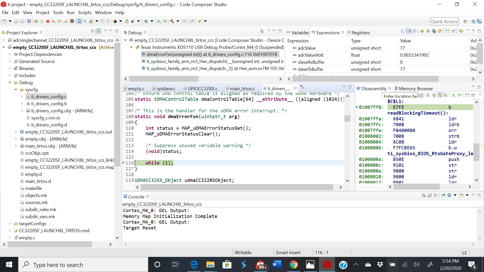
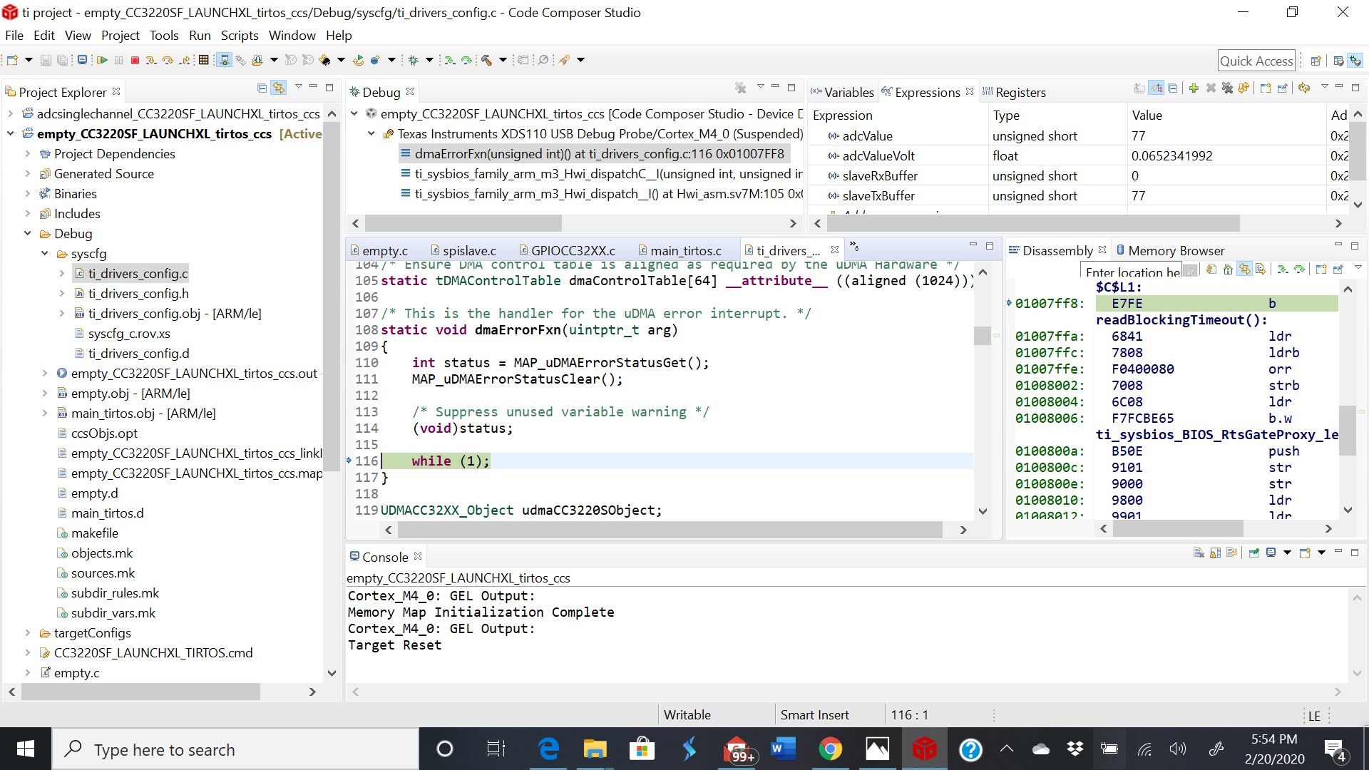
  • Thank you for your reply, The slave(CC3220sf) is getting stuck in a DMA function. I have added the screenshot for it. I don't know how to fix it. I'm struggling for hours with this problem. Any solution would be a great push for me. 

    thank you.

  • Varun,

    I have moved your thread to CC3220sf organization. Some one from that team should respond to your query on dma error function.

    Regards,

    Manoj

  • Hey Manoj,

    I still haven't heard back from anyone regarding the dma error. 

    Thanks.

    Varun

  • Hi Varun,

    The typical reasons you would end up in dmaErrorFxn is passing a pointer to an invalid address, or calling a new transfer before the previous one is complete. Can you verify your adcValue? It looks like you are directly assigning it to the buffer.

    Best regards,

    Sarah

  • Hey Sarah,

    I'm trying to transfer the adcvalue through spi. So I assigned it to the slaveTx buffer. How else should I do it? 

    Thank you

    Regards

    Varun

  • Hi Varun,

    SPI_transfer expects an array, like in the original spislave example:

    unsigned char slaveTxBuffer[SPI_MSG_LENGTH];

    You need to copy the contents of adcValue into this array.

    Best regards,

    Sarah

  • Hey Sarah, 

    Thanks for the help. I changed it according to your advice, The data seems to flow from Master(TMS320F28379D) to Slave (CC3220SF) but not the other way round. Also the data which I receive at the slave from master seems to be incorrect and not able to understand where the problem is. 

    Can you help?

    Thanks.

    Regards

    Varunkumar

  • Hi Varunkumar,

    How are you now copying the data into the transfer buffers?

    Can you try starting with the basic spi_slave and spi_master examples using two CC3220 LaunchPads? You can add your ADC implementation to the SDK examples and send the data back and forth to verify you have the correct format before debugging with the TMS320: http://dev.ti.com/tirex/explore/node?node=AJSfuJZZeSex2TkSjqSCnA__fc2e6sr__LATEST

    Best regards,

    Sarah