This thread has been locked.

If you have a related question, please click the "Ask a related question" button in the top right corner. The newly created question will be automatically linked to this question.

TMS320F280049C: SDK Lab guide

Guru 56033 points
Part Number: TMS320F280049C
Other Parts Discussed in Thread: DRV8320

SDK Lab guide leaves out some very important details of 5.1 settings being prerequisite. My motor got really hot after auto ID and 1st run. SDK has default 20Hz preset for full scale frequency. So how anyone know that was intended if they don't dig several guides looking for 5.1 info or burn up motor!

How are we to know 20 Hz is intended or required full scale frequency for InstaSpin motor auto ID? Also prior to auto ID all 3 motor phases are on full +Vbus level and very dangerous for HV motors. It is industry best practice to keep phase voltages OFF during idle time, why TI engineers not fowling best accepted practice?

5.1
Software Prerequisites
Below are the parameters that require configuration by in the user's software to manage the motor signals
required by InstaSPIN's FAST observer. Each parameter is discussed in this section.
• IQ full-scale frequency - set to motor's max electrical frequency with 20-30% headroom
• IQ full-scale voltage - set to motor's max voltage with 20-30% headroom
• IQ full-scale current - set to motor's max measurable current with 20-30% headroom
• Max Current - set to motor manufacturer's max current (peak) with 0% headroom
• Decimation rates - multiple loop rates and settings
• System Frequency - set to MCU's max CPU clock speed
• PWM Frequency - default is 20 KHz, increase with lower inductance motors
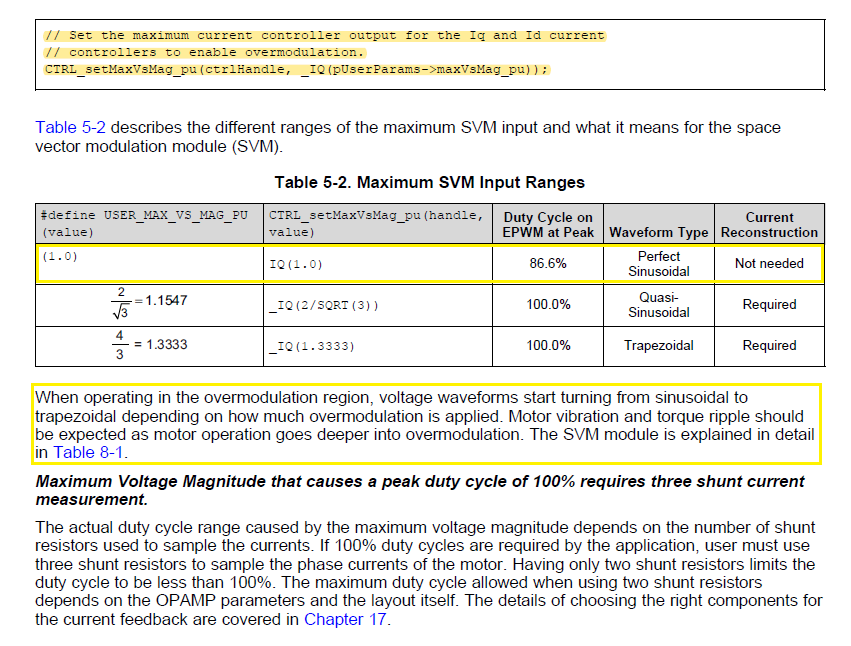
• Max Duty Cycle - 100% duty use 3-shunt current measurements

Below user parameters SDK mentions to preset in user.h no others:

A few values can already be populated in “user.h” before motor parameter identification.
 USER_MOTOR_TYPE = MOTOR_TYPE_PM or MOTOR_TYPE_INDUCTION  Motor type must be known and entered in this parameter.
 USER_MOTOR_NUM_POLE_PAIRS  Number of pole pairs of the motor
 USER_MOTOR_MAX_CURRENT  Maximum nameplate current of the motor
 USER_MOTOR_RES_EST_CURRENT  The motor will have to initially be started in open loop during identification. This value sets the peak of the current used during initial startup of the motor. If the motor has high cogging torque or some kind of load, increase this current value until the motor will start spinning. After motor identification, this value is never used.
 USER_MOTOR_IND_EST_CURRENT  Must be zero for ACIM motors. For PMSM motors this value can be set to the negative of the current used for USER_MOTOR_RES_EST_CURRENT. For example, if USER_MOTOR_RES_EST_CURRENT is 1.0, then USER_MOTOR_IND_EST_CURRENT can be -1.0.
 USER_MOTOR_NUM_POLE_PAIRS  Number of pole pairs of the motor
 USER_MOTOR_RATED_FLUX  Must be zero for PMSM motors. For ACIM motors the rated flux should be set to nameplate values calculated as follows:
USER_MOTOR_RATED_FLUX = SQRT(2)/SQRT(3)*Rated_VAC/Rated_F So for a 220VAC motor with a rated frequency of 60 Hz, then the rated flux would be:
USER_MOTOR_RATED_FLUX = SQRT(2)/SQRT(3)*220.0/60.0 = 2.9938
 USER_MOTOR_FLUX_EST_FREQ_Hz  A starting point for this frequency if the motor is a PMSM motor is 20.0 Hz, and if it is an ACIM motor, a good starting point is 5.0 Hz.

  • Some confusion as motor ID starts out spins rotor several thousand RPM smoothly then gets real coggy vibrating even hot and have to abort run. What is going on with motor ID even using square wave commutation, no sinusoidal attributes? Why does auto ID start to vibrate motor violently? Never have these issues with 6 code FOC with this same motor. What am I misunderstanding in the InstaSpin user guides?

    GUI after stopping auto motor ID when vibration gets really bad.

  • And settings; 

    //! \brief Defines the R/L estimation frequency, Hz
    //!
    #define USER_R_OVER_L_EST_FREQ_Hz (150)
    
    #define USER_MOTOR_VOLT_MAX_V (42.0)  

    has some effect to arrest cogging during ID test (160Hz peak) but still cogs/vibrates like crazy for later Run, after ID. Also CCS debug only allow 1 time motor ID even after pause restart. The SW refuses to renter motor ID test after it has set ID flag and we clear the real time flags to 0x0. InstaSpin SDK GUI must quietly be updating XDS110 firmware, every time it was run then CCS9.1 debug wants to update XDS110 firmware again. Firmware update should not be occurring repeatedly!

    The 3 phases wave forms are NOT sinusoidal they are 100% trapezoidal as described by user guide below. The waves shape is anything but trapezoidal as it is pure square wave after ID and run to user set Hz speed! There is a difference where trapezoidal valley/s will have sine attributes, missing in DRV8320 phase voltages during motor Run. The user guide Literature Number: SPRUHJ1H does not discuss the VsMagnitude (below) as it has been implemented in the SDK!

    USER_MAX_VS_MAG_PU can go up to 1.0, in global IQ format, or _IQ(1.0), if current reconstruction is
    not used. For further discussion and examples, see Labs 10a-x.

    //! \brief Defines the voltage vector magnitude
    #define USER_MAX_VS_MAG_PU (1.0)\#define USER_MAX_VS_MAG_PU (0.5)
    
    //! \brief Defines the reference Vs magnitude in per units allowed
    //! \ Set the value equal from 0.5 to 0.95 of the maximum Vs magnitude
    #define USER_VS_REF_MAG_PU ((float32_t)(0.8) * USER_MAX_VS_MAG_PU)

    Besides this definition of the maximum voltage vector magnitude, a member of the controller object can be changed to allow changing the output of the current controllers, which is then the input of the space vector modulation (SVM). This is important to note, because even though the maximum voltage vector magnitude is defined in user.h to be a maximum of 1.0 (or 100%), the inputs to the SVM can go up to 4.0/3.0 = 1.3333 allowing overmodulation. An input into the SVM above 1.0 is in the overmodulation region. An input of 2/SQRT(3) = 1.1547 is where the crest of the sine wave touches the 100% duty cycle. At an input of 1.3333, the SVM generator produces a trapezoidal waveform. The following code example changing the output of the current controllers to 1.3333 allowing maximum overmodulation:

    // Set the maximum current controller output for the Iq and Id current
    // controllers to enable overmodulation.
    CTRL_setMaxVsMag_pu(ctrlHandle, _IQ(pUserParams->maxVsMag_pu));

    Perhaps the controller is remaining in over modulation after motor ID flag has been set? So the motor vibrates, shakes during Run mode up to the users new and higher Hz setting.


  • All the identification variables must be set according to the spec. of the motor, the values show in the guide are just a reference for the tested motor. You'd better debug and tune a new motor with CCS since the identification variables may be changed accordingly. The GUI is good for running the identified motor or re-identifying a similar motor.

  • Yanming Luo said:
    The GUI is good for running the identified motor or re-identifying a similar motor.

    The GUI is part of the SDK and should not be silently downgrading firmware as it is doing without user prompts to acknowledge.

    Yanming Luo said:
    All the identification variables must be set according to the spec.

    The point of InstaSpin is to spin any motor without knowing all the specifications. SDK already smoked one Nidec motor, CCS debug did not make any difference. The new Nidec vibration reduces after reducing current and excitation Hz default 300 why on earth is it set so high? So new motor again passes ID with minor low speed vibration but after ID the first run up to 150Hz shakes like an earthquake over heats phases.

    //! \brief Defines the R/L excitation frequency, Hz
    //!
    #define USER_R_OVER_L_EXC_FREQ_Hz ((float32_t)(100.0)) //300

    1. The 3 phases remain 100% modulated, there is absolutely no sinusoidal wave shape during Run. Why is there not sinusoidal wave being formed is_05lab at any point? Please verify with a x49c kit this condition is not proper according to FOC text. S6 is upside down from picture in all guides reversing site 2 pins.

    2. You don't find it odd the motor is being modulated 100% trapezoidal in both ID and Run mode? It seems there is a Bug in SDK code since it never disables over modulation after ID check as shown in above post and discussed in InstaSpin FOC user guide. 

    3. The InstaSpin FOC lab guide SPRUHJ1H–January 2013–Revised June 2019 is relating variable names (defines) that do not exist in the SDK. How is that even proper? 

  • BTW:

    The phases USER_MOTOR_Rs_Ohm is being reported by motor ID 1/2 what is measured via DMM. That would seem part of the problem why current is then double what is actually required to ID the motor. Perhaps accounts for 100% modulation and result of no sinusoidal phase voltages being developed. At the mid point of auto ID it would often slam the rotor to stop after reaching a rapid and high speed then start shaking get very hot. That behavior seems very contrary to how InstaSpin FOC is stated to work in several TI documents.  

  • 1. The GUI is for the InstaSPIN lab demonstration and needs the correct motor parameters are set in user.h. Unfortunately, that doesn't have a generic function as you expect.

    2. It's very difficult to identify the unknown motor without setting appropriate parameters including maximum current, injection current and running frequency for the motor. It should be an ideal solution, but we can't afford this till now.  

    Please post your user.h and some waveforms of the motor phase current that will help us to understand your question. Thanks!

  • The phases USER_MOTOR_Rs_Ohm is being reported by motor ID 1/2 what is measured via DMM.

    That's right. The measured Rs is line to line resistance, but the identified Rs is line to neutral resistance. Rs (line to neutral) = 0.5 * Rs (line to line).