This thread has been locked.

If you have a related question, please click the "Ask a related question" button in the top right corner. The newly created question will be automatically linked to this question.

CCS/LAUNCHXL-F28379D: F28379D Interfacing MPU-6050 via I2C Protocol

Part Number: LAUNCHXL-F28379D

Tool/software: Code Composer Studio

Hello.

Iam trying to interface MPU-6050 with my F28379D Launchpad via I2C. Iam unable to generate the clock on my SCL pin. I intend to use GPIO 104 and GPIO 105 for interfacing.

void Init_GPIO(void)
{
InitGpio();
EALLOW;
GpioCtrlRegs.GPBGMUX1.bit.GPIO104 = 0;
GpioCtrlRegs.GPBGMUX1.bit.GPIO105 = 0;
GpioCtrlRegs.GPBMUX1.bit.GPIO104 = 1;
GpioCtrlRegs.GPBMUX1.bit.GPIO105 = 1;
GpioCtrlRegs.GPDPUD.bit.GPIO104 = 0;
GpioCtrlRegs.GPDPUD.bit.GPIO105 = 0;
EDIS;
}


void I2CA_Init(void)
{
I2caRegs.I2CSAR.all = 0x0068;

I2caRegs.I2CPSC.all = 15;               //(SYSCLK = 160MHz)
I2caRegs.I2CCLKL = 10;
I2caRegs.I2CCLKH = 5;                  // (400 kbps-FAST MODE)
I2caRegs.I2CIER.all = 0x24;

I2caRegs.I2CMDR.all = 0x0020;

I2caRegs.I2CFFTX.all = 0x6000;
I2caRegs.I2CFFRX.all = 0x2040;

return;
}

Iam only able to see my SCLA pin getting high when checked through an oscilloscope(because of internal pullup)

Please Help

Thanks and Regards,

  • Natsu,

    Both your GPIO initialization code and I2C initialization code looks correct. But, where is the code which initialized the I2C as master / slave? I don't think you have attached all the I2C related code. Please check.

    Regards,

    Manoj

  • Thanks for your reply.

    The problem was with my SCL and SDA pins not able to get driven without external resistors.I externally connected both the pins with a 4.7K resistor and i was able to see the clock on the oscilloscope.

    The problem iam facing now is when i write the line : while(I2caRegs.I2CMDR.bit.STP==1);   // wait until the complete transmission has occurred

    it is stopping there forever and hence the clock and data transmit is also getting stopped.

    But when i remove that line, iam able to get continous clock and data...but iam only able to receive only 1 byte.

    Please Help.

    Uint16 Read_Data (Uint16 readreg)
    {
    Uint16 ID;

    while (I2caRegs.I2CSTR.bit.BB == 1); 
    I2caRegs.I2CSTR.bit.SCD = 1; 
    while(I2caRegs.I2CMDR.bit.STP == 1); 

    I2caRegs.I2CMDR.all = 0x2E20; // STT=1, STP=1, MST=1, TRX=1, IRS=1

    I2caRegs.I2CCNT = 1; 
    I2caRegs.I2CDXR.all = readreg;         //readreg = 0x75 (to read whoami register

    while (I2caRegs.I2CMDR.bit.STP == 1); 

    I2caRegs.I2CMDR.all = 0x2C20; // STT=1, STP=1, MST=1, TRX=0, IRS=1

    I2caRegs.I2CCNT = 1; 

    while (I2caRegs.I2CSTR.bit.BB == 1); 

    ID= I2caRegs.I2CDRR.all; 

    return ID;
    }

    void Write_Data (Uint16 writereg, Uint16 writedata)
    {
    while (I2caRegs.I2CSTR.bit.BB == 1); 
    I2caRegs.I2CSTR.bit.SCD = 1; 
    while(I2caRegs.I2CMDR.bit.STP == 1); 

    I2caRegs.I2CCNT = 1;


    I2caRegs.I2CDXR.all = writereg;

    I2caRegs.I2CCNT = 1;


    I2caRegs.I2CDXR.all = writedata;

    I2caRegs.I2CMDR.all = 0x2E20; 

    return;

    }

    Do i need to use interrupts to get different data?

    Thanks and Regards

  • Natsu,

    I have provided I2C write / read pseudo code. Hope this pseudo code helps you get your project moving forward.

     I2C Write pseudo code:

    1)      Wait until I2C bus is busy

     2)      Set I2CCNT = number of bytes to be transmitted and I2CSAR = slave address

     3)      Wait till I2CSTR.XRDY bit (I2CDXR register is ready to accept new data) is set

     4)      Write data to be transmitted using I2caRegs.I2CDXR = data;

     5)      Set I2CMDR = 0x6E20     //FREE + START + STOP + Master + Transmit + I2C out of reset + 8 bits / data byte

     6)      Check whether I2C registers are ready to be accessed(Wait till ARDY bit is set I2caRegs.I2CSTR.bit.ARDY)

     7)      Check whether I2C is received NACK from slave. If NACK is received, then:

    1. Generate STOP condition             (I2caRegs.I2CMDR.bit.STP   = 1)
    2. Clear NACK in I2CSTR register     (I2caRegs.I2CSTR.bit.NACK   = 1)

     8)      Continue from step3 if you need to transmit more data, if not, generate stop condition

    I2C Read pseudo code:

    1)      Wait until I2C bus is busy

    2)      Set I2CCNT = 2 (2 bytes for address of EEPROM and I2CSAR = slave address)

     3)      Wait till I2CSTR.XRDY bit (I2CDXR register is ready to accept new data) is set

     4)      Write data to be transmitted using I2caRegs.I2CDXR = data;

     5)      Set I2CMDR = 0x6E20     //FREE + START + STOP + Master + Transmit + I2C out of reset + 8 bits / data byte

     6)      Check whether I2C registers are ready to be accessed(Wait till ARDY bit is set I2caRegs.I2CSTR.bit.ARDY)

     7)      Check whether I2C is received NACK from slave. If NACK is received, then:

    1. Generate STOP condition             (I2caRegs.I2CMDR.bit.STP   = 1)
    2. Clear NACK in I2CSTR register     (I2caRegs.I2CSTR.bit.NACK   = 1)

    8)       Set I2CCNT = number of bytes to be received

    9)       Set I2CMDR = 0x6C20     //FREE + START + STOP + Master + Receiver+ I2C out of reset + 8 bits / data byte

    10)     Check whether I2C is received NACK from slave. If NACK is received, then:

    1. Generate STOP condition             (I2caRegs.I2CMDR.bit.STP   = 1)
    2. Clear NACK in I2CSTR register     (I2caRegs.I2CSTR.bit.NACK   = 1)

    11)     Wait till I2CSTR.RRDY bit is set

    12)     Read the contents from I2caRegs.I2CDRR

    13)     Once number of bytes set in I2CNT is received, master will automatically generate stop condition

    Regards,

    Manoj

  • Thank you for the pseudo code Manoj.

    But i can already see the clock and slave address on my SCL and SDA pins.

    The problem is iam unable to get acknowledge from the slave.SDA goes high on the 9th cycle of SCL right after slave address and (R/W) bit.

    I also tried writing according to the pseudo code but it is still the same.

    Iam operating SCL at 4kHz.

    I also used external pull-up of 4.7K ohms resistor for both SCL and SDA pins and disabled the internal pull-ups.

    I tried both the addresses 0x68 and 0x69 but in vain.

    Please Help.

  • If you don't get ACK signal (SDA pin pulled low) from slave, it means that slave didn't recognize its address from I2C Master.

    • Slave address of MPU6050 is controlled by AD0 pin. Did you make sure AD0 is pulled down (since you using slave address = 0x68h)
      • When AD0 pin is pulled low, MPU slave address = 0x68h
      • When AD1 pin is pulled high,MPU slave address = 0x69h
    • Probe I2C signals on I2C protocol analyzer to see whether I2C master is transmitting the right address
    • Check whether VIL / VIH level of MPU6050 is not violated
    • Noisy I2C bus can also miss up the timing and could be root cause of the problem. Probe I2C signals using oscilloscope and observe for any anomaly

    • I would also encourage you try SCLK = 100 KHz and make sure you're meeting the I2C timing requirement from duty cycle and rise time perspective.

    Regards,

    Manoj

  • F28379D VDDIO level are around 3.3V, what about MPU6050? If they are working in different voltage voltage ranges, then you might need to add level shifter.

    Regards,

    Manoj

  • Iam actually working with a GY-521 board and gave 5V from Launchpad-F28379D to Vcc pin of Gy-521.

    May i know how to calculate Input/Output Logic levels of both the Launchpad and Gy-521 practically?

    Iam sorry but iam very new to this environment.

    Please Help.

    Regards.

  • I can also see that the program stops sometimes when i try to probe the SCL/SDA pins.The program runs in a loop but as soon as i try to put the probe needle on the SCL/SDA pin,sometimes the clock and data stops.I have no idea what the reason is.

  • You don't need to calculate VIL / VIH level. This information should be provided in corresponding DS.

    In F28379D, VIL / VIH information is documented in "Electrical Characteristics" table. Also, I assume that you are using I2C pull-up resistors are connected 3.3v (or) VDDIO of launchpad.

    Regards,

    Manoj

  • I can also see that the program stops sometimes when i try to probe the SCL/SDA pins.The program runs in a loop but as soon as i try to put the probe needle on the SCL/SDA pin,sometimes the clock and data stops.I have no idea what the reason is.

    Did you succeed in getting ACK signal from your slave? This is our first step. If your logic level (VIL / VIH) don't match for F28379 and MPU6050 you will be to get them talk to each other.

    Regards,

    Manoj

  • MPU-6050 Electrical Characteristics :

    VLOGIC = 1.8+-5% or VDD = 2.375V-3.46V.

    VIH(min) = 0.7*VDD or 0.7*VLOGIC

    VIL(max) = 0.3*VDD or 0.3*VLOGIC

    VOH(min)=0.9*VDD or 0.9*VLOGIC

    VOH(min)=0.1*VDD or 0.1*VLOGIC

    I gave 5V to VCC pin of GY-521 which has a voltage regulator, and i havent connected any pullups right now.I gave a pull-up of 4.7K ohm earlier though now i have removed them.

    I didnt get the acknolwedge.

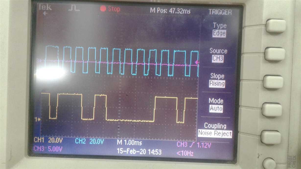
  • I have kept the read function in a for loop and this is what i can observe in my oscilloscope for one complete cycle.

  • Okay, VIL / VIH limits are based on VLOGIC level. Did you measure what is the voltage of VLOGIC?

    The voltage level on I2C SCL / SDA should satisfy the VIL / VIH requirements of both master and slaves in the bus. This is a basic requirement and has to be met to have them communication with each other.

    Also, you need to have pull-ups on both SCL and SDA and the choice of pull-up resistor value depends on VIL / VIH and rise time requirment.

    Regards,

    Manoj

  • The voltage on VLOGIC level is found to be 3.276V.(by multimeter on pin8 of IC).

    MPU-6050 :


    Vcc = 3.3V , VOL(max) = 0.1*VLOGIC = 0.3276 , IOL = 3mA.

    Rp(min) = 982.8ohms.

    Max rise time(tr) = 300ns , 

    I dont know how to calculate bus capacitance and since in the datasheet , it gave as <400pF, i assumed it to be 200pF

    Cb = 200pF.

    Rp(max) = 1770.329 ohms

    ControlCard :


    Vcc = 3.3V , VOL(max) = 0.4V , IOL = 4mA

    Rp(min) = 725 ohms

    Rp(max) : same as MPU6050

  • Natsu,

    What the pull-up resistor  you have on the SCL and SDA line? I believe you have a pull resistors connected to 3.3V and not 5.0v? correct?

    Bus capacitance, Cb depends on the I2C bus length, input capacitance of the I2C slave attached to I2C bus.

    Regards,

    Manoj

  • Natsu,

    In your earlier post, you have mentioned you have pull resistor > 4 Kohms. This value is greater than the calculated pull-up resistor max you calculated above.

    Reduce the pull-up resistor value to say 1Kohms.

    If this doesn't work you need to check how MPU6050 device is powered. It is possible that MPU6050 device is incorrectly powered.

    Regards,

    Manoj

  • No. I actually gave pull-up resistors of 4.7K ohms to VCC which is 5V.The GY-521 board has internal voltage regulator to 3.3V

  • I would prefer to have pull-up resistor on 3.3v rail because that mean both master and slave are operating in the same VBUS. Having slave at 5v and master at 3.3 is not a good idea.

    Regards,

    Manoj

  • Thank you very much for your patience.

    I was able to create communication between them.The acknowledge is acheived.

    Although, I still have a problem reading them.

    My Az and Gx value is currently reading at 62300-62400 range.But the maximum values are from -32768 to +32768 correct?

    Ax value is around 16000 which is actually 1G which is correct and Ay is 200-300 which is near to zero(stable position).

    Gy and Gz also around 50-60.

    i was able to receive whoami bit as 0x68 which is slave address.

    Please Help.

  • I'm not familiar with MPU-6050. So, I can't provide any meaningful suggestion here. You may have to try your luck post this question MPU6050 forum group.

    Regards,

    Manoj

  • 16-bit signed output value can vary from -32768 (0x8000) to 32767 (0x7FFF). I'm wondering whether 62300 corresponds to -3236 (62300-65536 = - 3236) and 62400 corresponds to -3136 (62400 - 65536). Check whether you defined these variable as 16-bit signed (or) 16-bit unsigned?

    Regards,

    Manoj