This thread has been locked.

If you have a related question, please click the "Ask a related question" button in the top right corner. The newly created question will be automatically linked to this question.

SDK OnLIne vibration

Guru 55223 points
Part Number: TMS320F280049C
Other Parts Discussed in Thread: BOOSTXL-DRV8320RS

Why motor to vibrate near end of LC test and still be Identified=1 (is05_motor_id.c)? No matter what value USER_MOTOR_FLUX_EXC_FREQ_Hz, motor vibrates <550Hz at any RES/IND current setting (user.h). Yet RS, CL1, CL2, first part LC very stable rotor, identified seems to write bad data for last part of course LC and later Est_State_Online vibrates. Oddly inverter PWM has very little if any sine wave artifact but seems ok accept for the random out of phase pulses randomly bucking the rotor field on all 3 phases. 

Inverter PWM has odd glitching, vibration smooths out >510Hz (5.1Krps), still random rotor field bucking occurs. This 12 pole PM motor runs flawless from 6 step commutation (6.2Krpm) via another MCU. This brand new x49c launch pad with BoostXL-DRV8320RS and motor SDK should seemingly not have PWM glitching issues. It would not be logical to test this HW on much larger PM motor under hard commutation as PWM glitching occurs on test bench expendable motor.

The BoostXL-DRV8320RS installed Site 2 and wonder if ePWM or PGA path errata, some how causing motor vibration? TI engineers please to confirm even remedy glitching PWM issue Site 2, MCU B silicon. No PGA 4, 6, 2 filters enabled Site 2. No blanking window codes (is05_motor_id.c). Site 2 ePWM generators GPIO order (A0,1 - B6,7 - C2,3) jumps over B generator ePWM module for D middle phase. It seems PinMux B6,7 is generator D so order seems odd. Rom calls to Park/Clarke expect out of phase signals? I see code (hal.h) ADC samples (Id/Vd) array[n] order compensates but is that actually working? Why is motor vibrate when it was extremely smooth OL, CL1,CL2 is 20Hz but last part LC has vibrates rotor? How can LC vibration be remotely correct SW behavior with intended purpose? Has TI confirmed both Site1 & Site2 produce the exact same motor ID conditions? Why would Site1 be consider placement drv8320rs by engineer to cover up launch pad LED's and only 1 booster pack? That would simply be clumsy investigation at best.

1. ePWM: An ePWM Glitch can Occur if a Trip Remains Active at the End of the Blanking Window?

2. PGA: Output Filter Path is Not Supported?

  • A much larger PM low motorVars.Rs_Ohms starts to vibrate near 98Hz and less noticeable than smaller PM via high .Rs_Ohms.  One can actually feel the vibration difference between 6 step and SVPWM commutation. It seems the output wave form below suffer some kind of timing issue. We have SVPWM tables in another TI MCU and sector Uout transforms produce better looking sine wave without added rotor vibration. 

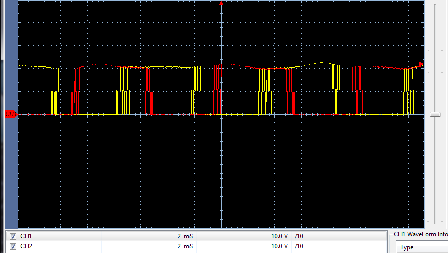
    Very small to very little sine wave occurs below VBus level as falling edges are not sin/cos curved into the next PWM period. Would we not expect more sine wave attribute to be produced inside the falling edges? The sharp edges from Gnd to VBus seems to be the cause of vibration more noticeable in smaller motors.

    Capture is DRV8320RS phase outputs A, B.

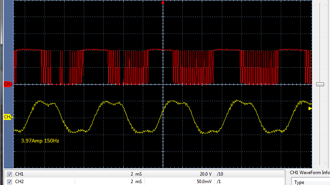
  • Double Dc Bus voltage 42V/8A and below CH2 4.5Amp sine wave has inflection, motorVar.speedRef_Hz = 150Hz, 0.500Krpm.

    Setting  motorVars.speedRef_Hz to say 160Hz and current oscillates 7-8A audible high frequency and CH2 has funky shape like above post. Why does CH2 sine wave have inflections and little to no rotor vibration occurs <100Hz but does >150Hz? 

    So the UserMotor == MyMotor has rotor inertia entry Kgm2 (user.h) and is05_motor_id.c should then over write code to set pUserParams->Kctrl_Wb_p_kgm2 code (user.c)? Note: MyMotor inertia Kgm2 = 3.528383e-001 for large rotor mass.

        else
        {
            pUserParams->flag_bypassMotorId = false;
    
            pUserParams->BWc_rps = MATH_TWO_PI * (float32_t)100.0;
            pUserParams->BWdelta = (float32_t)8.0;
    
            // 3.0 * pUserParams->motor_numPolePairs * 0.1 / (2.0 * 0.00001);
            pUserParams->Kctrl_Wb_p_kgm2 = (float32_t)3.0 *
                                           pUserParams->motor_numPolePairs *
                                           (float32_t)(0.001) /
                                           (float32_t)(2.0 * 0.000001);
        }


  • Both sites have been tested for all the labs with Teknic_M2310PLN04K and Anaheim_BLY172S_24V motors in motorControlSDK. Not all motors as you expected are validated.

    1. No. PWM is turn off immediately if there is a fault and trig the TZ.

    2. Not using the filter output of the PGA limit to the boosterPack, but using the filter logic of the CMPSS for overcurrent protection.

    Please post your user.h and show us which state (motorVars.estState) you met the vibration problem.

    Generally, you need to tune the identification variables in user.h according to the spec. of the motor as we have replied to you in other threads.

  • Yanming Luo said:
    Please post your user.h and show us which state (motorVars.estState) you met the vibration problem.

    This other motor large custom high efficiency SPM no specific settings exist but 6 step not cause minor high frequency vibration near >150Hz. The little Nidec motor vibrate like crazy >100Hz. Custom motor rotor mass 38 pounds, 20 pound sprocket so it play hell to vibrate this rotor as much. It seems the short PWM periods on either side of the 32µs ON cycle gets out of phase with mainISR 32µs high time period causing sustained vibration certain frequency, not as much low LC motor.

    The high LC motor vibration was terrible >100Hz. Have another 13Krpm 24v PM with similar 1.2A peak to try later this week. Our (float32_t) (2.0 * USER_MOTOR_INERTIA_Kgm2) part of motor id cause huge problem with true rotor inertia derived FEM. So we have to still use the fall through inertia calculation (user.c) otherwise WbFlux formula cause deceleration Voltage drop of PWM signals as user may reduce motorVar.SpeedRef_Hz=150 to even 145, very bad. Perhaps the formula (pUserParams->motor_ratedFlux_Wb = USER_MOTOR_RATED_FLUX_VpHz / MATH_TWO_PI) is the major difference between both methods?

    large PMSM typically voltage >150V is no problem only increases speed. As stated above post end of LC state has motor vibrations for high inductance motor, 3.1ohms L to L. The big motor just vibrates high frequency harmonic, sometimes feel vibration in metal brackets.


    Can poor sine wave samples of ADC inputs as I find one place in jscript (is02_offset_gain_cal.c) not set correctly for PWM gen D. Please answer why sine wave has odd inflections, are they more power supply related or ADC sample related? Why is there no sine voltage cycles, was expecting some sine voltage Vd not just sine current Id? It is quieter than 6 step on start up but >150Hz has similar winy sound come from rotor cooling holes.  

    Yanming Luo said:
    1. No. PWM is turn off immediately if there is a fault and trig the TZ.

    It don't trip faults at all and the Tz DC sub module (18.11) also failed to force DAC-A/B faults. The PWM outputs remain ON state all labs, no modifications.

  • The code as written user.c is bugged and does not auto switch inertia formula method when user has inertia defined user.h. Adding #ifdef below CCS code verify bool checks an error  (USER_MOTOR_INERTIA_Kgm2) if test when user adds define user.h.

    #else
    //#error No motor type specified (wrong conclusion) 
    #endif
    
        }
        else
        {
            pUserParams->flag_bypassMotorId = false;
    
            pUserParams->BWc_rps = MATH_TWO_PI * (float32_t)100.0;
            pUserParams->BWdelta = (float32_t)8.0;
    
      /* Is motor intertia user.h ? */      
     #ifdef (USER_MOTOR_INERTIA_Kgm2)
     {
    
    	pUserParams->Kctrl_Wb_p_kgm2 = (float32_t)3.0 *
                    pUserParams->motor_numPolePairs *
    		pUserParams->motor_ratedFlux_Wb /
    		 (float32_t) (2.0 * USER_MOTOR_INERTIA_Kgm2);
     }
    #endif
    else
     {
           	/* Is not motor intertia user.h */
          	pUserParams->Kctrl_Wb_p_kgm2 = (float32_t)3.0 *
    					   pUserParams->motor_numPolePairs *
    							(float32_t)(0.001) /
    							(float32_t)(2.0 * 0.000001);
     }
    
    } 

  • Stated above vibration occurs near end of LC state with high impedance motor 3.1ohms L-L it remains Online all frequency. Low impedance motor has high frequency vibrations the metal brackets, not present via 6 step commutation. Perhaps the PWM smaller periods need to have sine slope on either side 32µs ON times rather than so many sharp single periods. Seemingly if the rotation angle is correct each Uout sector via transforms there should be little to no added stator or rotor vibration on either motor inductance. 

  • Yanming Luo said:
    2. Not using the filter output of the PGA limit to the boosterPack, but using the filter logic of the CMPSS for overcurrent protection.

    We also try to force DAC-A/B trip event and ePWM Tz sub module ignores fault conditions. Have yet to see nFault disable ePWM-A/B output drive. Fact is the faults flag variable (nFault bit) was set and PWM drive was not latched to low state, it remain high. Add HAL_disablePWM() call into wait loop of is05_motor_id.c and still no PWM outputs ever low. Of course code was added to enable DAC advanced forced events too. Seems like errata in trip zone sub module since OC events seem to have tripped Tz2 bit, never disable PWM drive low. The drv8320rs nFaults set to trigger (retry) if supply droops UVLO, loads dragging down DC bus voltage. Yet no nFault flags check ever disable ePWM drives "we had to manually disable is05.js!" each time this may come up, motor got very hot locked rotor. Disable user.c lock rotor time wait flag check seem to help stop lock rotor after ramp up constant speed, some stable speed wait time added too. 

    static inline void HAL_disablePWM(HAL_Handle handle)
    {
        HAL_Obj *obj = (HAL_Obj *)handle;
    
        EPWM_forceTripZoneEvent(obj->pwmHandle[0],
    							EPWM_TZ_FORCE_EVENT_OST | EPWM_TZ_FLAG_DCAEVT1 | EPWM_TZ_FLAG_DCAEVT2);
        EPWM_forceTripZoneEvent(obj->pwmHandle[1],
    							EPWM_TZ_FORCE_EVENT_OST | EPWM_TZ_FLAG_DCAEVT1 | EPWM_TZ_FLAG_DCAEVT2);
        EPWM_forceTripZoneEvent(obj->pwmHandle[2],
    							EPWM_TZ_FORCE_EVENT_OST | EPWM_TZ_FLAG_DCAEVT1 | EPWM_TZ_FLAG_DCAEVT2);
    
        obj->flagEnablePWM = false;
    
    
        return;
    } // end of HAL_disablePWM() function
        //
        // Waiting for enable system flag to be set
        //
        while(motorVars.flagEnableSys == false)
        {
        	int x;
        	for(x=0, x > (2.0 * USER_EST_FREQ_Hz); x++;)
        	HAL_disablePWM(halHandle);
        }

  • Yanming Luo said:
    Please post your user.h and show us which state (motorVars.estState) you met the vibration problem.

    It was posted above. Today run more test labs on big motor, vibration has low harmonic (SpeedRef >125Hz), harminic and vibration goes away @125Hz. Odd thing is after 30 minutes motor run time @125Hz 2nd low harmonic goes away.

    It seems the low harmonic undertone leads to large rotor vibration, we can actually hear.  Harmonic could be DC power supply related since this is same supply used with high impedance motor, vibrated too! Perhaps why FW lab13 current (Idq_ref_A.value[1]) 4 amps jumps to 8 amps when FW is enabled and voltage also starts to droop near I peak of this supply? 

  • You need to set the correct the USER_MOTOR_MAX_CURRENT_A to limit the current according to the motor, board and power supply. What's the target frequency and feedback frequency when you enabled the FW?

  • Yanming Luo said:
    You need to set the correct the USER_MOTOR_MAX_CURRENT_A to limit the current according to the motor

    As you can see 6.2A was set (user.h) for the limit at 40v bus volts. The 40vdc supply produce 9A from two 20vdc 4.5A in series. Suspect that may be partially to blame for FW not speeding rotor above 150Hz as Online current show peaks 7A, current clamp concurred. Most concerning is the current peaks (CH2 second capture) have an odd detent. That seems to indicate an extended period from over modulation lab 5 Online motor run.

    Yanming Luo said:
    What's the target frequency and feedback frequency when you enabled the FW?

    Target was 150Hz and feed back quickly reduced. The only time feed back hertz remained stable was after RsOnline enable was set prior to FW enable, then current spiked but frequency remain stable as RsOnline self extinguished.  And we know how that finally ended......

    I was mistaken about the harmonic vibration of large motor was (mostly) bearing grease related. Have not had BoostXL-drvV8320rs to confirm it either way. 

  • I was testing two motors; Small Nidec 12 pole 3.1ohm L-L, custom motor 0.4ohms L-L via setting (user.h) above.

    Was testing custom 36 pole out runner for FW effect watching PWM voltage CH1, current clamp CH2. The voltage would start to droop FW was left enabled for more than few seconds. Yet current would rapidly peak >7 amps no matter USER_MOTOR_MAX_CURRENT_A set to 6.2A. 

    I don't regularly check L-L phase ohms and notice user.h RS online is lower compared to 0.4ohms. Oddly DMM checks L-L ohms @21°C ambient prior to motor run and yes it's cold in here.

  • The USER_MOTOR_MAX_CURRENT_A is used to limit the torque current which is the output of the speed controller, not the phase current of the motor that is a different value.

    Recommend using lab05 to identify the motor parameters, not using the measured resistance by a DMM, especially a low resistance motor.