This thread has been locked.

If you have a related question, please click the "Ask a related question" button in the top right corner. The newly created question will be automatically linked to this question.

TMS320F28034: CBC being set at start of code before main modules reached

Part Number: TMS320F28034

In my code at startup i do the following:

EALLOW;

Comp1Regs.COMPCTL.bit.COMPDACEN = 1; //Power up Comparator 1 locally
Comp1Regs.COMPCTL.bit.COMPSOURCE = 0; //Connect the inverting input to the internal DAC
Comp1Regs.DACCTL.bit.DACSOURCE = 0;

EDIS;

Then i have a CBIT in the main state machine evaluating the trip flag where i clear the trip condition 4 times then set a warning on the 5th time.

CBC_TripFlagStatus = EPwm1Regs.TZFLG.bit.CBC;

if (EPwm1Regs.TZFLG.bit.CBC == 1)

{

if(CBC_LimitCounter <=4){CBC_LimitCounter++;}

if(CBC_LimitCounter>=5){

Warning10_CBCLimit =1;

}else{

EPwm1Regs.TZCLR.bit.CBC=1; // Clear Trip condition

}

}else{

if(CBC_LimitCounter !=0){CBC_LimitCounter--;}

Warning10_CBCLimit = 0; // CBC Limit not tripped

}

However, what i notice is that the CBC is being tripped at startup before it even gets to the CBIT part of the code. Is there some other setting or register setting that i need to set to ensure it doesnt get tripped at startup every power cycle on the controller?

Thanks for any help u can provide.

Abe

  • Abe,

    By default the output of the internal DAC is code 0, so if there is any positive voltage on the COMP1A pin(ADCINA2) will be a logical high out of the module.

    When you enable this path into the ePWM trip zone, assuming the COMP1 output is high, it will register to the module as a high going edge since it was 0 before the connection.

    I'd make sure and give the DAC (using DACVAL) a value either at or above your intended trip range before enabling the complete path.  This will ensure the output is a logical low (0) into the TZ.  You can then modulate it based on your system need once everything is set up.

    Let me know if this is the issue, or if you were already setting the DAC we can look a bit deeper.

    Best,

    Matthew

  • Matthew:

    thanks for the reply and it did seem that was the issue and hence i set the DACVAL to a higher value at startup during the initialization of the controller. I then set it to a more representative value. This resolved the startup issue.

    One other question:

    - the DACVAL accepts 0 to 1023 as its input to set the CBC limit and its transferable to the PWM output module which is also 0:1023. if my PWM command going in from the control modules are 0:4095 for 0:2 Amps, what is the general guideline to use for setting the CBC limit to be 2.25A if 0 to 4095 (and ie..0:1023 in the PWM command) is 0 to 2A?

    Appreciate the clarification,

    Abe

  • Abe,

    Both the ADC(12bit 0-4095LSBs) and DAC(10-bit 0-1023) have a similar full scale range.  The ADC is targeted to 0-3.3V no matter the VDDA; the DAC is a simple resistor ladder based off VDDA, so it may scale a bit depending on your VDDA supply.

    My point being with either you'll need to determine whatever shunt resistor will scale the 2.0A or 2.25A to a certain voltage and set the DAC accordingly.  If there is some relationship you want to keep based on the ADC converted value, you could just right shift the 12-bit value by 2 LSBs to convert to the approximate 10-bit value and then load that with some +/- safety range.

    Let me know if you have further questions.

    Best,

    Matthew

  • Matthew:  

    thx, one additional question.   Does the DACVAL and hence the comparator take into effect the ADC calibration at startup? In other words, should i be adding the ADC offset value (which i subtract out in the comparator after i read the ADC value) to the DACVAL for the CBC limit?

    thanks for the input, 

  • Abe,

    This is a really great question, just in terms of thinking through the error terms that would be present in the system(hopefully I can give an adequate answer :))

    The offset calibration that happens at startup, should be removing any offset error that the ADC would introduce into the calculation if the ADC was run natively.  So, whatever ADC conversion that happens after this during normal operation will have that error removed before you see it in the ADC Result registers.  

    However, there can still be some amount of gain error that is still in the result, with a maximum of +/-60LSBs as defined in the datasheet.  Since this is a multiplicative error it is more helpful in this case to think of it as such, or a max of 1.5% error term based on the ideal code.  So if your analog voltage is ideally 1.65V(half of the 3.3V FSR) then the max gain error at this voltage would be 30LSBs, and so forth based on your votlage range.  

    You'd need to account for this potential error if you did the right shift of 2 bits as I mentioned since it would make the ADC value that much too high or low. 

    Typically I think most systems have a absolute keep out value that you could just translate into the 10-bit DAC value.  Perhaps there could be some initial sweep at startup to tune this threshold on each device?

    Let me know if you have more questions.

    Best,

    Matthew

  • Matthew:

    thanks for the feedback. One final question if you dont mind.

    During my CBC CBIT i look at the TZFLG bit and keep clearing the bit until a persistence reached. This is running in a 1ms loop. See the code below. However, when i induce the fault to trip the CBC and take away the condition, i still see the counter incrementing and it doesnt get decremented. This means that it never sees the TZFLG.bit.CBC get cleared. Is there something else i need to do to clear the trip condition other than what i have below?

    CBIT code:

    CBC_TripFlagStatus = EPwm1Regs.TZFLG.bit.CBC;
    if (EPwm1Regs.TZFLG.bit.CBC == 1)
    {
    if(CBC_LimitCounter <=9999){CBC_LimitCounter++;}
    if(CBC_LimitCounter>=10000){

    Warning10_CBCLimit =1;
    }else{
    EPwm1Regs.TZCLR.bit.CBC=1; // Clear Trip condition
    EPwm1Regs.TZCLR.bit.DCAEVT2=1; // clears the DCAEVT2 event trip condition
    CBC_TripValue = 5;
    }
    }else{
    if(CBC_LimitCounter !=0){CBC_LimitCounter--;}
    Warning10_CBCLimit = 0; // CBC Limit not tripped
    CBC_TripValue = 10;
    }

    I never see CBC_TripValue go back to 10 when i remove the condition that caused it (and i was still under 10000). I also added the following to the else where the clearing happened just to cover my bases:

    EPwm1Regs.TZCLR.bit.DCBEVT2=1; //
    EPwm1Regs.TZCLR.bit.DCBEVT1=1; //
    EPwm1Regs.TZCLR.bit.DCAEVT1=1; //
    EPwm1Regs.TZCLR.bit.INT=1; //

    Is it something to do with the TBCTR?

    Appreciate any help,

    Abe

  • Abe,

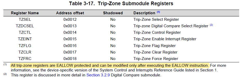
    Are you executing EALLOW before writing to the TZCLR register?  Note the highlighted statement from the TRM:

    -Tommy