This thread has been locked.
If you have a related question, please click the "Ask a related question" button in the top right corner. The newly created question will be automatically linked to this question.
Tool/software: Code Composer Studio
Hello,
I am a new user of f28335. I am working on data acquisition of PWM inverter. I am stuck at designing of PWM by using f28335.
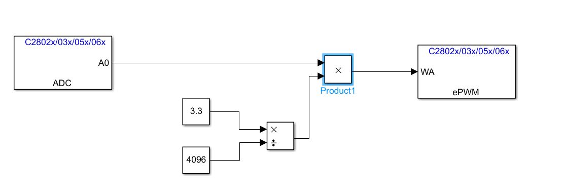
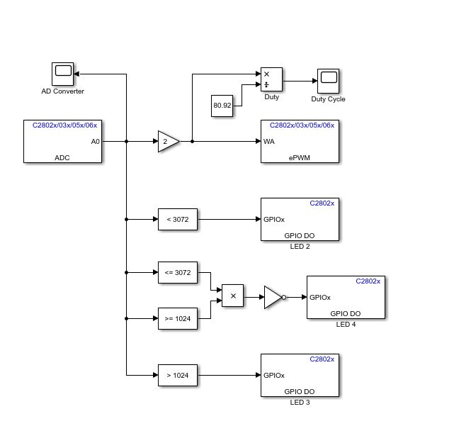
The input of ADC is 0-3 V. the output range of ADC is 0-4095. I would like to know the Simulink block that will convert the count number to 0-3 V. and how do I know the ADC output for the given input of 0-3 V.
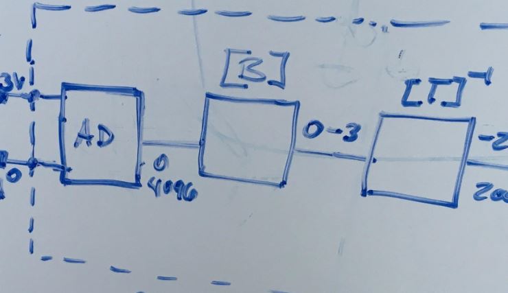
I would like to know about the block [B] in my following diagram. and how can I design it in MATLAB simulink?
Take a look over here :
Conversion is done by calculating V = Vref/ADbit * ADValue. In your case this would be 3.3V/4096 * ADsampleValue.
It would look like this.
Another example how to work with MATLAB and C2000.
Try to work with code viewer on, it is a great way to learn programming c2000 MCUs.
Happy coding :)
Martin
Thanks for your response.
Would you please help me with how can I use code viewer?
I am not sure which Version of Matlab you use and you will need the Embedded Coder, Simulink Coder and MATLAB Coder.
In my case in the app tab in simulink there is a button called Embedded Coder. Click on it and a few options should appear. Search for a button called "view code". If you click it a window on the right should appear with your actual generated code. It highlights related lines when you hover over simulink blocks.
Try changing all kind of things and click on build to see how it changes your actual DSP code. I learnt so much using this method.
Also in the Diagnostic Viewer you should have an option to open the project in Code Composer Studio if you need more control or for debugging.
Have fun.
Thanks again! it's really helpful. One other thing it is possible to display ADC signal at code composer studio?
or graphically see the output at CCS.
I am not sure about Code Composer Studio but you can display the output in simulink on a scope. Very useful but bear in mind that it is slow. I couldn´t reach much more than a few kHz then often the dissapeared on the scope or had missing samples. So start with slow sampling times and signals. Maybe 1kHz sampling frequency and a 50Hz sine or something like that. Please follow the link for explanation of external Mode:
de.mathworks.com/.../parameter-tuning-and-signal-logging-with-serial-external-mode.html
You can actually tune the parameters of you model in real time with this method.