This thread has been locked.

If you have a related question, please click the "Ask a related question" button in the top right corner. The newly created question will be automatically linked to this question.

FOC SDK ADC SF

Guru 56218 points

Part Number: LAUNCHXL-F280049C
Other Parts Discussed in Thread: INA240, BOOSTXL-DRV8320RS, MOTORWARE, EK-TM4C1294XL, TIDA-00778

Having issues to set the ADC scale factor for INA240 set 40mV/A, reference mid supply 1.65v and Voltage SF are not so precision. A big SPM will stall at start of LC (20Hz) unless USER_MOTOR_RES_EST_CURRENT_A is set very high (12.5A) and well above SF for PGA shunts (7mohm) x13 gain (91mV/A), 35A full scale! Assuming the PGA's are not rail-rail amps gives us a 3.2v ADC FS so 42A was over the sample margin (user.h).

High EST current R/L samples cause (motor.vars_RsOnline_Ohms) reading to be hundreds of ohms when actually 0.56 ohms. Perhaps is not producing good ID values via USER_ADC_FULL_SCALE_VOLTAGE_V = (330) , nominal DC input is now 41V?  

1. Where are the mV/A current formula/s or SF in the SDK for I_A sample conversions, so the math can be made more precision for off board sensors? It seems PGA 7mohm shunt was ok for 42A but going to 80A the 2mOhm shunt gives 40mV/A x20 gain of INA240A1. That seems to work to keep motor spinning entire LC test but all other values go to bad monkey.

2. It seems the USER_ADC_FULL_SCALE_CURRENT_A is missing USER_IQ_FULL_SCALE_CURRENT_A part shown SPRUHJ1H–Page 255 and offset does not seem to get it accurate enough. The test does not explain how to fix the SDK for other testing modes.

3. How to improve (motorVars.Rs_Ohm) measure or what needs to be tweaked for the higher voltage USER_ADC_FULL_SCALE_VOLTAGE_V ((float32_t)(330.0))  and USER_VOLTAGE_FILTER_POLE_Hz((float32_t)(348.794)) so the L-L Ohms can be more accurate? Oddly starts out ok then crosses the true value but ends test with fictional 1mohm value? Reducing R1/R2 EMF, Buss voltage divider values helps to push up ADC precision to 4 LSB versus 1LSB.  

4. Swapping the current source ADC=A,B,C to a 1-1 (SOC is I_A) produces higher currents and motor spins in LC mode, but motor.vars_RsOnline_Ohms is then in the hundreds of ohms. 

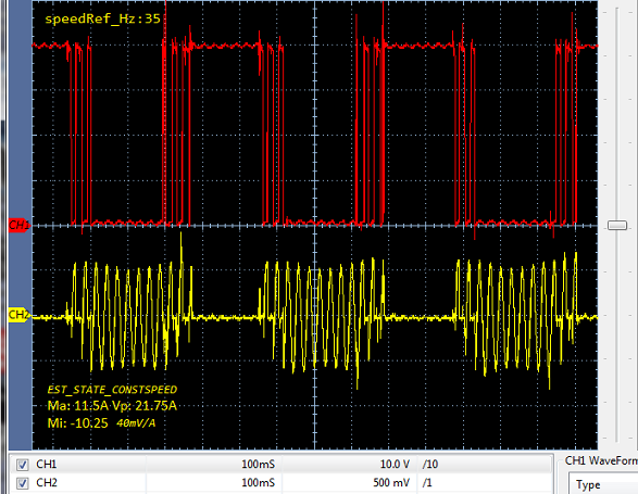
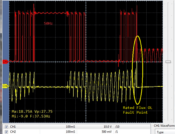
Oddly BoostXL-DRV8320rs motor stalls during LC too but ID did seem to get close enough values to run large SPM to 550Hz. The new Nidec 20v motor  vibrates from basic setting (user.c) but run much longer time than  pUserParams->estWaitTime[EST_STATE_LS] = 0; The newly added LC states (ramp, course, fine, done) are missing in is05_motor_id.js.

    // set the current scale factor
    HAL_setCurrentScaleFactor(handle,USER_CURRENT_SF);

    // set the voltage scale factor
    HAL_setVoltageScaleFactor(handle,USER_VOLTAGE_SF);

//! \brief Defines the maximum current at the AD converter
//!        BOARD_BSXL8320RS_REVA, Gain=12, INA240 Gain=20
#define USER_ADC_FULL_SCALE_CURRENT_A         ((float32_t)(80.00))

//! \brief ADC current offsets for A, B, and C phases
#define IA_OFFSET_A    (-40.00)   //-21.428 ~=0.5*USER_ADC_FULL_SCALE_CURRENT_A 
#define IB_OFFSET_A    (-40.00)   //-21.428 ~=0.5*USER_ADC_FULL_SCALE_CURRENT_A 
#define IC_OFFSET_A    (-40.00) 

  • Reduced EMF Bus voltages divider networks: R1=100k, R2=5k and re calculate the FS values did help to zoom in on motorVars.Rs_Ohm value closer to reality but....

    Motor 36 poles still stalls in LC test even BoostXL board but ID keeps going to produce incorrect (motorVars.flux_VpHz = 26v to 42v). Increasing rotor speed Hz/sec + reducing LC wait times helps to reduce values, not fix. If we ramp up rotor speed (30Hz-60Hz) it trips DC faults switching into state EST_STATE_RATEDFLUX_OL.  Previously increased CMPSS TripINx points (2158/68) counts.

    The LC current wave form (stalled rotor) is more square wave in this test. How this value was even close via BoostXL board amazes as the rotor was stalled during LC. Point is Online BoostXL motor ran to 550Hz and with custom DC inverter it won't go even 20Hz with the very high (motorVars.flux_VpHz).

    So dividers (R1/R2) are changed from what TI used for BoostXL conflicts with user.h method of determining SF precision! Needless to say this is not a good sign for future upward mobility using these new formula values. 

    1. How is USER_VD_SF to be determined? Used below formula to calculate new SF=1.549 thus motorVars.VdcBus_V = 42.4v for the USER_ADC_FULL_SCALE_VOLTAGE_V   ((float32_t)(63.510))

    Formula:
    USER_VOLTAGE_SF = USER_IQ_FULL_SCALE_VOLTAGE_V / USER_NOMINAL_DC_BUS_VOLTAGE_V  to replace USER_IQ value.

    2. Does VD_SF effect motorVars.flux_VpHz or what user.h values determines how this Vp/Hz is determined? 


  • 1. MotorControlSDK uses the floating-point and SI unit format, it doesn't use the PU format as motorWare. You just need to set the correct USER_ADC_FULL_SCALE_VOLTAGE_V and USER_ADC_FULL_SCALE_DCBUS_VOLTAGE_V based on your hardware board. The current and voltage sensing circuit parameters should be designed according to the motor to achieve a good resolution. I don't think you need to change more control parameters as you mentioned above except for the related motor parameters in user.h.

    2. No. You don't need to change USER_VD_SF that is just used to limit the output of Id controller, it should be always less than 1.0. motorVars.flux_VpHz is the motor parameters, flux linkage which can be identified by lab05 or get from the motor manufacturer.

  • Yanming Luo said:
    You don't need to change USER_VD_SF that is just used to limit the output of Id controller

    Oddly EST_STATE_IDRATED is tripping CCMP TripINx faults motor is speed 40Hz as not to stall as it did during LC. The odd part being the phase current reduced 6A after startup then peaks again to near 18A in EST_STATE_CONSTSPEED, this allows current to stabilize prior to entering EST_STATE_CONSTSPEED. Why is the phase current magnitude increasing in steady state velocity?  

    Yanming Luo said:
     motorVars.flux_VpHz is the motor parameters, flux linkage which can be identified by lab05 or get from the motor manufacturer.

    The problem is the R1/R2 values seem to have an odd effect on this parameter being ridiculously high. Perhaps there is some reason a (user.h) SF is causing this reading to grow so large? Seemingly this parameter value is dependent on the hardware phase angle flux linkage in each sector. So we should be able to put in all the values BoostXL motor ID lab5 created and there be no problems, right?

    Yet the motorVars.RsOnLine_Ohm is no where close to BoostXL (0.155892089) and R1/R2 + SF changes (0.222270876). The control suite formulas were there for good reason and simply dividing UserADxFS/4096 does not appear to have fine enough granularity to compensate. 

  • Yet try to use settings from BoostXL setting flag motorVars.flagEnableUserParams = true does not fill in the information from user.h into lab05. This lab allows free run Hz after ID and the flag was seemingly not ignored via GUI but is via CCS debug.

    As for the faults occurring via EST_STATE_IDRATED and rotor vibration during several LC states, phase current abruptly changes to square wave. It oddly looks like Offset calculation is again running. Should the _IDRTAED be a trapezoidal wave form? It does change amplitude as it grows then shrinks but the SPM motor hates it like this pandemic.

    Software should say motor must not stall during EST_STATE_RATEDFLUX_OL. Try to increase USER_MOTOR_FLUX_EXC_FREQ_Hz but it was being forced to 20Hz in is05.c so user.h can't adjust Hz speed unless we modify SDK! Assumed such was done without much thought since SPRUHJ1H page 264 Fig.16-9 ~ 50 Hz for [1 uH < Lphase < 10 uH] and ~ 20 Hz for [10 uH < Lphase < 1000 uH]. Seemingly it has more to do with plow speed during high buzz saw action. lol

  • Above scope capture looks just like EST_STATE_RS has run in place of EST_STATE_RATED_FLUX_OL. We noticed it ramps up the very same way then ramps down via trapezoidal wave, rotor is stalled! Perhaps explains sudden OC trips no matter CCMP threshold was set 2358 (68Amp) no higher.. Even stiffened the CCMPx DC filter to ignore H/L transients. Point was EST_STATE_ID is for ACIM only.

            // Configure digital filter. For this example, maximum sense values
            // were used for the clock prescale, sample window size, and threshold.
            CMPSS_configFilterHigh(obj->cmpssHandle[cnt], 32, 24, 13);//4,3,2
            CMPSS_configFilterLow(obj->cmpssHandle[cnt], 32, 24, 13);//4,3,2

  • Yanming Luo said:
    You just need to set the correct USER_ADC_FULL_SCALE_VOLTAGE_V and USER_ADC_FULL_SCALE_DCBUS_VOLTAGE_V based on your hardware board

    Obviously that is not entirely true and you base such belief the motor ID state machine is working correctly as intended. At least from our view bypass motor ID and current parameters (user.h) motor only hunts for zero angle rotor jerking movements. For one bypass lock rotor flag was set false default state (user.h) should be true for PM device type and (if) tested (is05.c) for ACIM motors only checked user.h define. Often caused instant lock up small SMP motor rotor even though EST_STATE_LOCKROTOR time wait = 0. If the small motor managed to not lock rotor it would vibrate and in the case of large rotor mass there was 0Hz increase as current ramps up. So 35Hz set user.h remains 35Hz during state ramp up where low Kgm2 mass rotor might accelerate several hundred hertz. That may not have been intended but occurs never the less.  

    Also noticed is05.c calls setupControllers() (labs.h) over rides Kctrl_Wb_p_kgm2 previously set (user.c) inertia configuration using user.h inertia value. It seems odd how this value is being pushed around like a hockey puck.

    ID motor does run speed 35-50Hz produce sinusoidal current ramps up just prior to State Rated Flux RL seems to enter StateRS again. The state machine is not sequencing all the wait states specified (user.c). Seemingly SDK did not intend to produce trapezoidal waves and Stall / Over current the motor during lab5 motor ID? This current ramp up seems to be state ramp up occurring during wait time StateConstSpeed or CL has been silently entered.

    Set const wait to zero, current still build up (scope capture) but quickly trips fault during what should be the 1st part of  EST_STATE_RS. Scope capture above seems to infer EST_STATE_RS is again run. BoostXL some how avoids current fault conundrum presented above scope evidence of severe issues and misbehavior in custom inverter hardware.

    1. Why does EST_STATE_RS not have sinusoidal attributes trips OC faults and vibrates rotor of small motors?

    2. Does TI allow their engineers to investigate customer reports of severe impact of SDK firmware to preform as intended? 

  • 6.5.6 CTRL_State_OnLine and EST_State_RatedFlux

    6.5.6.1 Current Ramp-Down
    The first thing that happens when identifying the flux is for a closed-loop to be enabled internally by the motor identification state machine. This closed-loop is not enabled by the user. Current consumption lowers to a minimum current value needed to keep the mechanical load spinning at the same frequency when this closed-loop is enabled. The slope at which current is lowered is a fixed value, Rs estimation per second divided by 3. The dividing factor of 3 was selected during design of the motor identification process to provide a slower slope.

    And that is where it all goes a muck! Note instant current peak somewhere inside CL as RatedFluxOL was enabled. It seems like another state RS since the current wave being produced (only 20Hz) for EstOLrated was trapezoidal, stalled rotor.  The current slowly grew from Ma: 4.2A up to this peak (CH2) during ramp up. but the current was to be ramp down 0.33 seconds.

    RatedFlux _CurrentSlope = USER_MOTOR_RES_EST _CURRENT / 1sec or 12.2A * 1/3 = 4.06A/s

  • So if we bypassMotorid=true use setting from user.h, (EST_STATE ONLINE, EST_TRAJ_STATE_ONLINE) there is no rotor acceleration up to target speed motorVars.speedRef_Hz = 550Hz. The rotor only slides from point to point and can quickly over heat NFETS.

    Yet bypassMotorid=false trajectory engine spins rotor up to target motorVars.speedRef_Hz = 50Hz for motor ID. It would appear the SF for current is not working so well but only for the BoostXL predetermined 7mv/A shunt. Perhaps LC was tripping faults with BoostXL but DC CCMP's did not report OC error if the TripINx was not aligned to the MUXn used for CCMP2, CCMP4, CCMP6. I don't recall CCMPx DC ever tripping single fault as they are configured properly to do so!

            /* Check the fault flags register, assert status */
            if(HAL_getPwmEnableStatus(halHandle) == true)
            {
                if(HAL_getTripFaults(halHandle) != 0)
                {
                    motorVars.faultNow.bit.moduleOverCurrent = 1;
                    
                    SCIprintf(">>FaultNow->: %x\n", ui32TripFaultNow);
                }
            }
  • The problem with tripping faults is due to peak current SF is not the true ADC scale factor based on shunt value and or amp gain. So the INA240 gain 20, 2mohm shunt gives 40mV/A. Yet 20x gain is almost doubled inside ADC and odd SF has to be cut in half or more. The current SF is not doing what it should be doing!

    //! \brief Defines the maximum current at the AD converter
    //!        BOARD_BSXL8320RS_REVA, Gain=12, INA240 Gain=20
    #define USER_ADC_FULL_SCALE_CURRENT_A         ((float32_t)(80.00))

    Oddly reducing FS to 40A then EST_STATE_RATEDFLUX_OL actually proceed 50Hz and buzz motor like chain saw eventually trips DC fault.

    So the ADC SF is not based on science and only works with BoostXL-DRV8320RS in very controlled 7mohm 12x PGA gain.
    The INA240 should work well with 80A SF but it seems CCMPx DC sample window prescale and delay threshold values are below the 80A SF! We are nearly at the top of ADC scale 
        // Set the initial value to half of ADC range
        uint16_t cmpsaDACH = 3858;//2048
        uint16_t cmpsaDACL = 3868;//2048
    
            // Configure digital filter. For this example, maximum sense values
            // were used for the clock prescale, sample window size,
            // Prescale: clocks between samples, Sample window: Not >32,
            // threhold: < Sample window/2 but 1 less than filter threshold
            CMPSS_configFilterHigh(obj->cmpssHandle[cnt], 456, 24, 11);//4,3,2
            CMPSS_configFilterLow(obj->cmpssHandle[cnt], 456, 24, 11);//4,3,2

  • Yanming Luo said:
     USER_ADC_FULL_SCALE_DCBUS_VOLTAGE_V based on your hardware board.

    The divider seems to cause numerical saturation from the calculated filter pole. Below values nearly same as SDK and BoostXL resistor divider network.

    Notice often produce fictitious .Ls_d_H/.Ls_q_H(9.99999997e-07) perhaps numerical saturation related? Seems IQ value missing from SDK and BoostXL odd WA by keeping ADC voltages above imaginary threshold via resistor divider values?

    For instance numerical saturation occurs (motorVars.flux_VpHz) more often produces results 20v-68v. Following SPRUHJ1H page 234-235 guidance was no help. How does divider network R1=5k, R2=100k, C=100nF make x49c ADC threshold above a sweet spot of FAST estimator calculations?

    Perhaps try these same divider values BoostXL and confirm filter pole is actually constraining (motorVars.flux_VpHz) as it seems to be missing constraints. Seeing these very odd SDK results on dedicated DC inverter that works very well via 6 step commutation (EK-TM4C1294XL) is very discouraging! Seemingly PGA's buffer amps should have been used for FAST estimator voltages into x49c ADC? Attempting 80 amps seems a far reach for the SDK as it has been developed for BoostXL-DRV8320rs and no other TI production systems, such as TIDA-00778.

    Yet I was very impressed BoostXL to spin our very large SPM without much effort, using ID (Lsd_H/Lsq_H) data from stalled rotor OL/LC testing. How was it possible to obtain values from a stalled rotor that actually spin rotor 550Hz via Rst_Traj_Online? We can not duplicate this, yet ramp up spins motor 50Hz but fails after ID via above divider values to run same Hz speed. Perhaps the voltage divider used by FAST is extremely sensitive and should have PGA buffers in this version?

    NOTE:
    • Typical values for USER_VOLTAGE_FILTER_POLE_Hz fall between 300 Hz < pole <400 Hz.
    • USER_VOLTAGE_FILTER_POLE_Hz ≥ 200 Hz.
    IQ_FULLSCALE_FREQUENCY_Hz must be set to a value < 4.0 × USER_VOLTAGE_FILTER_POLE_Hz to avoid numerical saturation.

    //! \brief Defines the maximum voltage at the AD converter
    //!        full scale voltage of AD converter, EMF 392.7
    #define USER_ADC_FULL_SCALE_VOLTAGE_V         ((float32_t)(61.510))
    //! \brief Defines the analog voltage filter pole location, Hz
    //!
    #define USER_VOLTAGE_FILTER_POLE_Hz           ((float32_t)(294.522))

  • The INA240 wins hands down as a more compatible current measure than PGA amps, even with filters enabled. CMPSSx was expecting mid supply +1.65v threshold via PGA outputs, seems to fail x3, x6, x12 gain. 

    Yet the INA240 bidirectional current measures (mid supply) appear to properly control CMPSSx as SDK configured. Though easily trip fault bit (OVC) even with DC filter sample window delayed by 456 clocks, wide 24 window, every 11 samples of. It would seem the CMPSSx ramp generator needs to be configured and was omitted as engineer did not witness PGA's giving issues.

    Perhaps since CMPSSx did not trip ePWM faults it was assumed PGA's output was set to mid supply via external DAC, kept below 2048 counts! The CCMPx low DAC output inversion existed below count 2048, <1.65v. The INA240 input into the analog sub module CMPx_LP0/HP0 via J5 pin 45, 46, 48 into R19, R22, R25 (4K7) seems to confirm this finding. 

  • Which TI's EVM kit are you using? It seems like we don't provide any example instaSPIN-FOC labs on a kit with INA240.

    As replied to the other threads you posted, please make sure that the current and voltage sensing signals are good for motor control on your own hardware board first, and ensure the device configuration and parameter settings are defined correctly based on your board.

  • Yanming Luo said:
    Which TI's EVM kit are you using?

    lauchXL x49c with custom DC inverter and the results are not so good. Oddly the offset currents set in SDK (FOC) do Not relate to 1/2 ADC full scale as depicted in SPRUHJ1H–January 2013–Revised June 2019. The negative offsets are shown (0.005) or 5%, not 1/2 full scale. I tested offsets 5% so (-40.0) is actually (-0.4A) 5% but it didn't make any difference or cause any harm, why?

    //! \brief ADC current offsets for A, B, and C phases
    #define IA_OFFSET_A    (-0.40)   //-21.428 ~=0.5(0.005%)*USER_ADC_FULL_SCALE_CURRENT_A 
    #define IB_OFFSET_A    (-0.40)   //-21.428 ~=0.5*USER_ADC_FULL_SCALE_CURRENT_A 
    #define IC_OFFSET_A    (-0.40) 

    The problem was DC current required for rated flux (50-60Hz) rotor speed drags 40v down to 20v as it starts up. It either tripped immediate DC fault or at some point inside Rated flux tripped fault. Again the BoostXL rated the flux on stalled rotor (20Hz) and there oddly was online rotor acceleration. That was not true via INA240 set mid supply 1.65v as there was no acceleration after motor ID ran 20Hz. So motor had to run 55-60Hz at very high current or immediately trip DC fault.  

    The point of booster packs is not for customers to stay bedded to or with them, rather to advance into target designs. Hence nifty JP connectors allow booster removal so customer can then leverage custom hardware via the same Jn headers! Our other test DC inverter allow direct connection to headers via short jumper wires. This inverter kit is effective >150vdc via EK-TM4C1294XL and should have no problem with LauchXL 49c SDK (FOC) yet failed for reasons unknown.

  • It seems like the current offset values are not correct as you mentioned above,  the values should be equal to the half of the ADC full-scale value with the sign based the board.

    Please check if the current and voltage sensing signals are good for the motor drive on your own inverter board first, and the parameters are set correctly in the user.h accordingly. if not, don't go to the next step.

    You might go back to lab02, lab03, and lab04 to verify the hardware board.