This thread has been locked.

If you have a related question, please click the "Ask a related question" button in the top right corner. The newly created question will be automatically linked to this question.

TMS320F28377S: Thermal Properties

Part Number: TMS320F28377S


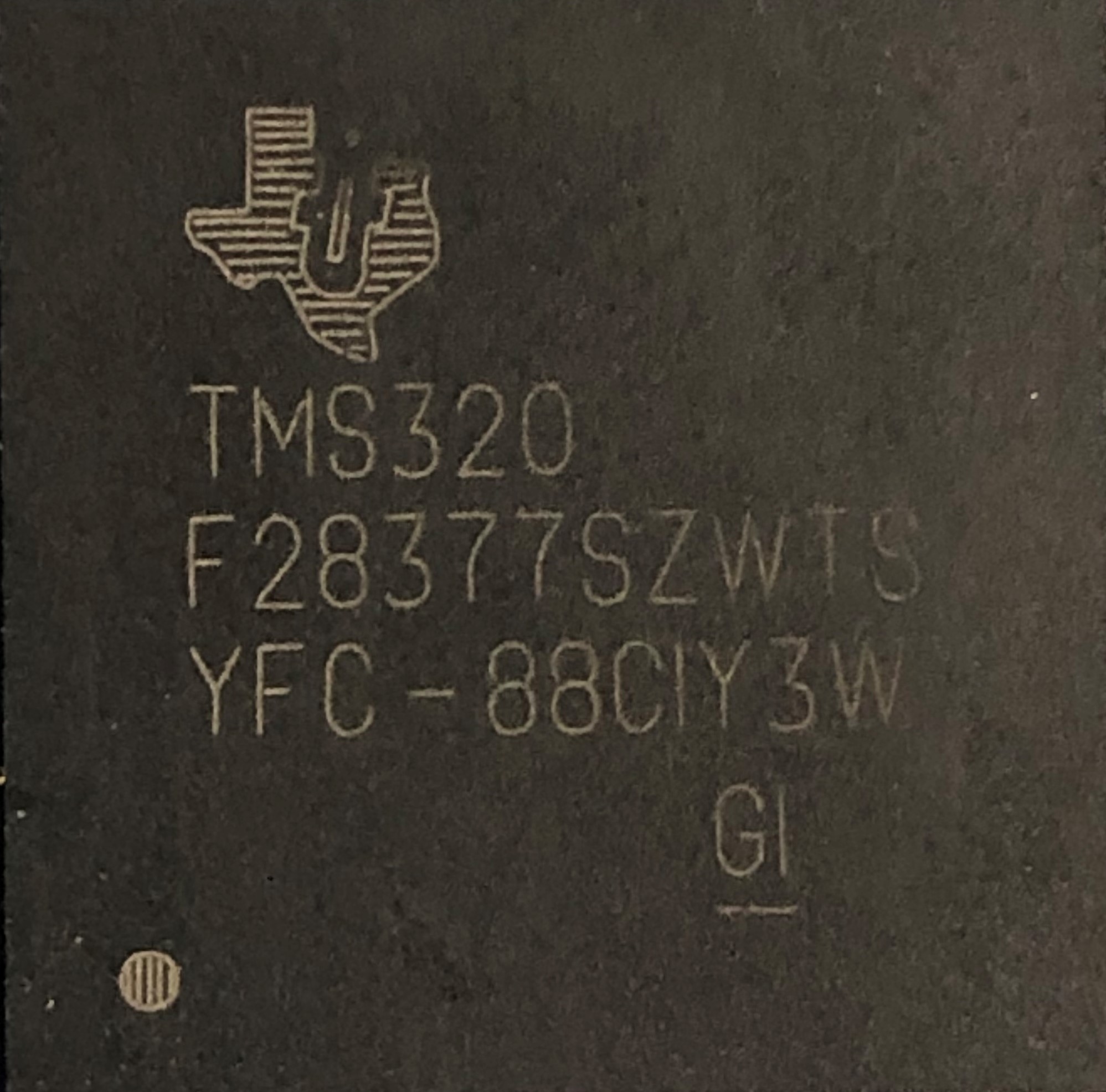
The attached photos show 2 similar chips used in our prototype build of an inverter.  They are behaving differently when ambient temperature dips below -15 degree C.  Can anyone tell by the chip label what the differences are between the 2 chips?  Our application needs chips that can operate to -40 degree C.

  • Aleks,

    this information can be found in the datasheet. Looking at those devices, they are:

    • Same wafer fab
    • Same Silicon revision
    • Produced at the same time
    • Assembled in two different lots, but at the same site

    What does the following mean?

    Aleks Vilis said:
    They are behaving differently

    These devices are about as similar as two devices can be. Of course from time to time there are device to device variations and occasionally failures. If we know what the devices are doing I may be able to help you work towards a solution.

    Regards,
    Cody

  •  Hi Cody,

    I work with Aleks and I can shed some more light on the issue here.

    We were running HALT tests on inverters that have control boards built with TMS320F28377S MCUs. The control board that we received from our CM had the MCU with following code: $4C-93AHHTW. When chamber temperature was reduced we found that the MCU stoped working at around -15°C to -20°C range. Our goal was to operate down to -40°C. Once the temperature is increased, and the MCU is power cycled, it operates normally.

    We tested reset lines - there was no activation of the reset signal down to -40°C

    Monitored X1 oscillator signal - no changes to oscillator down to -40°C

    We repeated tests with a different control boards with the same  MCU batch $4C-93AHHTW and observed the same behavior.

    We then had several boards reworked as follows:

    • Two boards with original $4C-93AHHTW MCU batch  were reflowed.
    • Three boards had MCU replaced with $4C-93AHHVW MCU batch we purchased from Digi-Key 

    Both batches of the MCU still had the same behavior, shutting down at around -15°C to -20°C

    We had previously built a small batch of control boards locally for FW development and the MCUs have this code: YFC-88CIY3W


    These boards were successfully operating down to -40°C without any signs of MCU hanging. These control boards were built from the same SCH and PCB designed files and using the same components as the boards we received from CM.

    Is there any possibility that $4C-93AHHTW  and $4C-93AHHVW batches of MCUs might have some issue with low temperature operation?

  • Igor,

    thanks for the information! Because there was some conflicting information with what Aleks had written please confirm my understanding in the two bullets below.

    1. $4C-93AHHTW  and $4C-93AHHVW are both having some error at ~-15°
    2. Previously YFC-88CIY3W was used and had no issues down to -40°C

    From what I have read it is still unclear to me if the F28377 device is actually the problem or a symptom of the problem, please keep an open mind while working through this issue. To be perfectly clear I am not trying to dodge your question in anyway, we want to get to the root cause wither its directly related to the F28377 device or not.

    So, to actually find out whats going on were going to need to do a little bit of debug.

    Do you have access to a debugger while running inside of the temperature chamber?

    If we can observe the device while its at cold temp. it may help point out if the issue is something going on inside the device or if it related to an external support component.

    Its good that you observed XRSn and the clock input! Can you also observe VDD and VDDIO as well?

    Usually these circuirts are pretty robust, but it would be good to check anyway.

    Regards,
    Cody 

  • Cody,

    You are correct regarding our observations as you stated:

    1. $4C-93AHHTW  and $4C-93AHHVW are both having some error at ~-15°
    2. Previously YFC-88CIY3W was used and had no issues down to -40°C

    I forgot to mention that we also monitored all of the control board power rails including VDD and VDDIO and did not see any changes in voltages.

    We can definitely setup a JTAG connection during low temperature chamber run. Could we continue conversation via email, because I would like to involve our firmware lead? 

    Regards,

    Igor

  • Igor,

    For now lets keep it on the forum. If it gets to a point where we need to take it to email, we can.

    1. Does the emulator remain connected to the c2000 device at cold temp?
      1. assuming it remains connected, is it still executing code? does it get stuck in some unexpected function?
      2. assuming it disconnects, is there any 'heart beat' for the device that we could check if it is still operating? 

    Regards,
    Cody 

  • Hi Cody,

    We were able to run our unit in the thermal chamber with JTAG emulator connected and here is what we observed:

    1. The JTAG connection to the MCU is working on all boards down to -40 °C, and we were able to change the values of internal RAM memory locations and read them back correctly.
    2. On malfunctioning boards the MCU enters into the ILLEGAL_ISR routine at temperatures above -20 °C but below -15 °C. We did not investigate what causes the “Illegal Operation” to happen.

    I am hypothesizing that it might be possible for one or more BGA power rail and/or ground pins to disconnect at low temperatures and thus leave parts of the internal MCU circuits without power. Would this make any sense at all? Do you have any other ideas what could cause the MCU to enter illegal ISR?

    Regards,

    Igor

  • Igor,

    an illegal ISR is simply a routine that is branched to when the device executes an illegal instruction. For example attempting to execute 0xFFFF with a C28x CPU will trigger this.

    • Make sure that this actually was an illegal ISR that branched us to this code. If it was an illegal ISR you should have information saved to the Stack. You can use that information to determine what instruction was called
      • This is  a complicated and rare debugging methodology, and unfortunately the information is spread out across. a few documents. Start by reading the ITRAP description in the technical reference manual, and it will point to the other documents.

    While we do require that all VDD, GND and VDDIO pins remain soldered to the correct voltage, they are internally connected and would likely be OK as long as a number of them remained connected. 

    Illegal ISRs can happen for many reasons, code bugs are common, but device defects can cause them too. Determine if it was an illegal ISR, and use that information to determine what instruction caused it.

    1. Was this a logical piece of code that the CPU should have been executing?
    2. Can you single step through that code and get the same result?
    3. Does the core have to be running at full speed?
    4. Is the instruction located in RAM or Flash?
    5. Is it a valid instruction that has been corrupted, or is it a memory address that should have never been executed?

    If it is an Illegal ISR, that's good! And now we have something to start debugging.

    Thanks,
    Cody