This thread has been locked.

If you have a related question, please click the "Ask a related question" button in the top right corner. The newly created question will be automatically linked to this question.

LAUNCHXL-F280049C: Why current controller performance degrades above 400 Hz reference speed?

Part Number: LAUNCHXL-F280049C
Other Parts Discussed in Thread: BOOSTXL-DRV8323RS

Hi

I am using Launchpad and boostxl-drv8323rs to drive custom pmsm motor (Pole pairs = 14, Ls = 100.8424 uH, Rs = 102.324 mOhm, Rated RPM = 8000, Kv = 99 rpm/V). Controller parameters are calculated based on following set up in the code.

Current controller bandwidth BWc_rps = 2*Pi*1500

Damping factor BWdelta = 15.0  (Which also called frequency spacing parameter between current and speed controllers.)

Acceleration max Hz per second = 300

Vin = 24 VDC

Speed Control filter pole (USER_SPEED_POLE_rps) = 100 rad/s

Calculated PI controller values (in labs.h) are based on the above parameters work fine up to 380 Hz ref speed (1715 RPM). Even under the loading condition motor is driven by pure sine wave without much distortions. But above the 380 Hz speed, controller doesn't perform well and sine wave shows high switching ripple over fundamental waveform. Results didn't improve even after increasing the current controller bandwidth from 1500 Hz to 4375 Hz and speed controller gains as well. 

What could be the reason for this type of behavior? Would results improve by increasing the switching frequency (with out overrunning ISR)?

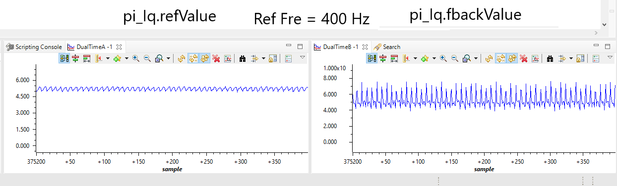
Below are the snapshots from the datalogger for Reference and Feedback values of Iq current for 380 Hz and 400 Hz ref speed.

#define USER_NUM_PWM_TICKS_PER_ISR_TICK        (1)

//! \brief Defines the number of ISR clock ticks per current controller clock tick
//!
#define USER_NUM_ISR_TICKS_PER_CURRENT_TICK     (1)

//! \brief Defines the number of ISR clock ticks per speed controller clock tick
//!
#define USER_NUM_ISR_TICKS_PER_SPEED_TICK     (10)


//! \brief Defines the number of current sensors
//!
#define USER_NUM_CURRENT_SENSORS               (3)


//! \brief Defines the number of voltage sensors
//!
#define USER_NUM_VOLTAGE_SENSORS               (3)

//! \brief Defines the system maximum input frequency, MHz
//!
#define USER_MAXIMUM_SCALE_FREQ_Hz    ((float32_t)(1000.0))

//! \brief Defines the system clock frequency, MHz
//!
#define USER_SYSTEM_FREQ_MHz       ((float32_t)(100.0))


//! \brief Defines the Pulse Width Modulation (PWM) frequency, kHz
//!
//#define USER_PWM_FREQ_kHz          ((float32_t)(5.0))      //5KHz PWM frequency
//#define USER_PWM_FREQ_kHz          ((float32_t)(10.0))     //10KHz PWM frequency
//#define USER_PWM_FREQ_kHz          ((float32_t)(12.0))     //12KHz PWM frequency
//#define USER_PWM_FREQ_kHz          ((float32_t)(15.0))     //15KHz PWM frequency
#define USER_PWM_FREQ_kHz          ((float32_t)(35.0))       //20KHz PWM frequency

  • The 400Hz should be ok for 20kHz if you mean the speed is electrical frequency. Don't set the PWM frequency to a value that is greater than 25kHz if the USER_NUM_PWM_TICKS_PER_ISR_TICK is 1, that means the controller (ISR) must be less than 25kHz limit to CPU bandwidth.

    You can check the motorVars.Vs_V if it's greater than or lose to userParams.maxVsMag_V. If yes, you might try to increase the dc bus input voltage to see what happens.

    And you might tune the current controller for high speed as well, don't use unique gains for all speed ranges.

  • Hi Yanming,

    Yanming Luo said:
    The 400Hz should be ok for 20kHz if you mean the speed is electrical frequency. Don't set the PWM frequency to a value that is greater than 25kHz if the USER_NUM_PWM_TICKS_PER_ISR_TICK is 1, that means the controller (ISR) must be less than 25kHz limit to CPU bandwidth.

    Ok so I reduced the switching frequency is 25 kHz and PWM_TICKS_PER_ISR_TICKS is 1. So no ISR overrunning issue. Btw I have tested 35 kHz switching frequency and it works fine without overrunning ISR since its execution time is about 27.5 us.

    Yanming Luo said:
    You can check the motorVars.Vs_V if it's greater than or lose to userParams.maxVsMag_V. If yes, you might try to increase the dc bus input voltage to see what happens.

    Here is the screenshot showing that motorVars.Vs_V doesn't go beyond userParams.maxVsMag_V in either case (above and below 400 Hz electrical frequency). Also, tried to increase the dc bus input voltage to 48 V but got no improvements in the results.

    Yanming Luo said:
    And you might tune the current controller for high speed as well, don't use unique gains for all speed ranges.

    I have varied the current controller bandwidth up to 2000 Hz but still no improvement in the results.

    1. Is the evaluation board boostxl-drv8323rs has some short of limitation?

    2. Is moment of inertia (USER_MOTOR_INERTIA_Kgm2) causing some problems?

     3. would increasing the switching frequency give better results since it is low inductance motor?

    4. It seems dynamic decoupling is missing in Current controller. Would that be the reason?

    could you provide some more insight on how to tackle this issue? Your help would be greatly appreciated. By the way simulation model seems to be working okay for high speed command.

    Motor Electrical Frequency = 425 Hz ---> 1821 RPM

    Motor Electrical Frequency = 380 Hz ---> 1628 RPM

  • Apparently, I had to make some hardware and software changes to solve this issue. The PI gains that I obtained are based on the Simulation and they work fine with desired RPM range. Because of the higher pole pairs of the motor, rated electrical frequency is in few kHz for rated RPM (i.e. 8000 RPM at 1.867 kHz).

    Voltage filter pole frequency decides cut-off frequency of the back-emf signal send to FAST for angle estimation.

    In simple term, voltage filter pole frequency decides the max electrical frequency (of back-emf) at which you can drive your PMSM motors. Which also allows FAST to estimate rotor angle based on the back-emf feedback signal. Default voltage filter pole was the limiting factor for electrical frequency and hence the max RPM we can get.

    Based on the default value, max electrical frequency (hence max RPM) you can spin your PMSM is around 380 Hz.

    //! \brief Defines the analog voltage filter pole location, Hz
    //!
    
    #define USER_VOLTAGE_FILTER_POLE_Hz           ((float32_t)(338.357)) // Default value
    

    Best,

    Amit