This thread has been locked.

If you have a related question, please click the "Ask a related question" button in the top right corner. The newly created question will be automatically linked to this question.

TMS320F28375S: Controller is behaving strange. VDD (1.2V) issue?

Part Number: TMS320F28375S
Other Parts Discussed in Thread: LMR10510, LM43602, UNIFLASH, LM2830

Hello.

I have a PCB with a TMS320F28375S. The situation is, that code execution in the controller stucks (controller hangs up?), when the different controller components are activated. I think the cause of the problem is the 1.2V-rail.

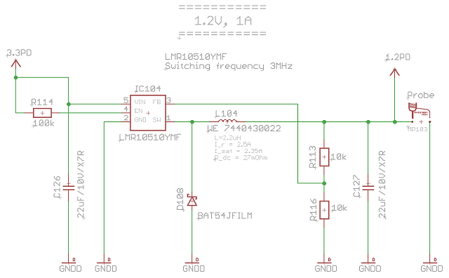
The PCB uses a switcher LM43602 to generate the 3.3V (Input 24V). The 1.2V are generate out of the 3.3V with a switcher LMR10510. I have no ferrites in series between the two rails. At each VDD pin I placed closely a 3.3uF capacitor. At each VDDIO pin I placed closely a 0.1uF capacitor. For VDDA, VDDOSC and VDD3VFL I did the same.

Notice to "placed closely": all decoupling capacitors are placed on the opposite board side to the controller. But I guaranteed the current flow through the capacitor from the power supply rail. That means: rail -> capacitor -> via (to controller board side) -> pin (of controller).

Observation: After adding a large 22uF capacitor "in front of the controller" to the 1.2V rail, the controller runs in particular. That means when stepping through the code with a debugger and activating the different controller components one by one with some delay, the controller finally runs and I can communicate via RS232. Nevertheless flashing of the device is still not possible.

I used a scope to find spikes on the 1.2V rail. I found nothing so far.

Questions:

1. Is the LMR10510 not suited for this controller?

2. Would it help to add some more capacitance to the 1.2V rail?

3. Would it help to add some ferrites between the 3.3V and 1.2V rail?

Thank you for your support.

Beste wishes, Marcus

  • Marcus,

    The 1A power supply that you are using should suffice for the microcontroller, is there anything else on your board that could also be drawing power from it? Are you saying that after adding the 22uF capacitor the code is running out of RAM, but not possible to Flash the device? Could you provide some more information on how the Flashing is not proceeding correctly, any error messages?

    Regards,
    PEter

  • Hi Peter and thank you for helping me.

    The controller is the only part connected to the 1.2V rail.

    Regarding the 22uF capacitor: after adding it, running the code from RAM is only possible when using the stepping function (stepping from line to line) of the debugger for the "InitSysCtrl()" function. After this function the controller runs. Without stepping during "InitSysCtrl()", the device "hangs up".

    Flashing: we tried it using "UniFlash" and the flashing option in CCS. CCS provides several error messages during flashing. Here is an excerpt from the beginning:

    C28xx_CPU1: Error: (Error -1044 @ 0x0) The debug probe reported an error. Confirm debug probe configuration and connections, reset the debug probe, and retry the operation. (Emulation package 6.0.14.5)

    C28xx_CPU1: Unable to determine target status after 20 attempts

    C28xx_CPU1: Failed to remove the debug state from the target before disconnecting.  There may still be breakpoint op-codes embedded in program memory.  It is recommended that you reset the emulator before you connect and reload your program before you continue debugging

    C28xx_CPU1: Error occurred during flash operation: Could not write

    0x00000064@Data: target is not connected

    C28xx_CPU1: Error occurred during flash operation: Could not read

    0x00130@Program: target is not connected

    C28xx_CPU1: Error writing the PLL values. (Flash algoirthm returned error code). Operation cancelled.

    C28xx_CPU1: File Loader: Memory write failed: Unknown error

    C28xx_CPU1: GEL: File:

    /home/ronald/workspace_v6_1/LDM44/Release_Flash/LDM44.out: Load failed.

    C28xx_CPU1: Error occurred during flash operation: Could not read register PC: target is not connected

    C28xx_CPU1: Error occurred during flash operation: Could not write

    0x0005F800@Data: target is not connected

    C28xx_CPU1: Error occurred during flash operation: Could not write

    0x0005FC00@Data: target is not connected

    C28xx_CPU1: Error occurred during flash operation: Could not write

    0x00000@Program: target is not connected

    In the meantime, I made some other observations. I was able to record the 1.2V with the scope. Hint: running the code from RAM without stepping (debugger).

    The first scope screenshot shows the 1.2V (purple) and 3.3V (yellow). I suppose the spike in the 1.2V occurs when the InitSysCtrl() is executed. After that spike the controller hangs up.

    Now I changed the inductor size of the LMR10510Y from 3.3uH to 2.2uH. The result shows the next screenshot. Again 1.2V purple and 3.3V yellow.

    Now the 1.2V (as well 3.3V) is disturbed with spikes continuously. But the controller now does not hang up. It runs from RAM. Trying to flash the device with CCS fails anyhow.

    My 1.2V schematic looks (now) as shown in the third screenshot.

    From my point of view, it seems the LMR10510 is having problems with the current demand of controller.

  • Marcus,

    The Flash is powered from 3.3V supply, (not the 1.2V). do you see anything happening on XRSn pin? If there is brown-out condition, this pin will drive reset signal low.

    Regards,
    Peter


  • Peter,

    meanwhile we solved the problem by using a different switcher. We now use a LM3674MF-1.2. Now we don't see any issues with the 1.2V rail. In between I tried a LM2830XQMFE, because this part has the same pinning like the LMR10510Y. But in the end flashing failed again with the LM2830. But now the LM3674MF-1.2 works fine. The key difference (from my point of view) between the LMR10510Y and the LM3674MF-1.2 is, that the latter one is a voltage mode switcher. Could that be the source for the voltage problems I faced?

    The good thing is, that the LM3674MF-1.2 only need two caps and the inductor. A fairly simple circut.

    Thank you for your support. Regards,

    Marcus

  • Marcus,

    Thanks for the update, I am glad you got this resolved


    REgards,
    PETer