This thread has been locked.

If you have a related question, please click the "Ask a related question" button in the top right corner. The newly created question will be automatically linked to this question.

CCS/TMS320F28335: Using "POWER_MEAS_SINE_ ANALYZER" in motor drive application

Part Number: TMS320F28335
Other Parts Discussed in Thread: C2000WARE

Tool/software: Code Composer Studio

Hi community!

I am using a TMS320F28335 DSP for controlling an induction motor drive. I want to measure the power and power factor of the motor. However, as you know, usually there is not any voltage sensor for measuring the phase voltage of the motor. Instead, the applied voltage to the motor can be detected by using the PWM signals (e.g., volt_calc.h). The question is that can I use the "POWER_MEAS_SINE_ANALYZER" from Power Measurement Library for this purpose? In the guideline document, it is mentioned that the measured voltage should put into the function as the input. Can I use PWM signals due to the lack of voltage sensor?

Where can I find a usage example of the POWER_MEAS_SINE_ANALYZER ? I have looked at "C:\ti\c2000\C2000Ware_DigitalPower_SDK_1_01_00_00\solutions\tidm_1000", however, the function "POWER_MEAS_SINE_ANALYZER_run" is not used in the code so I don't know how to put inputs to the function.

Regards

  • Lio,

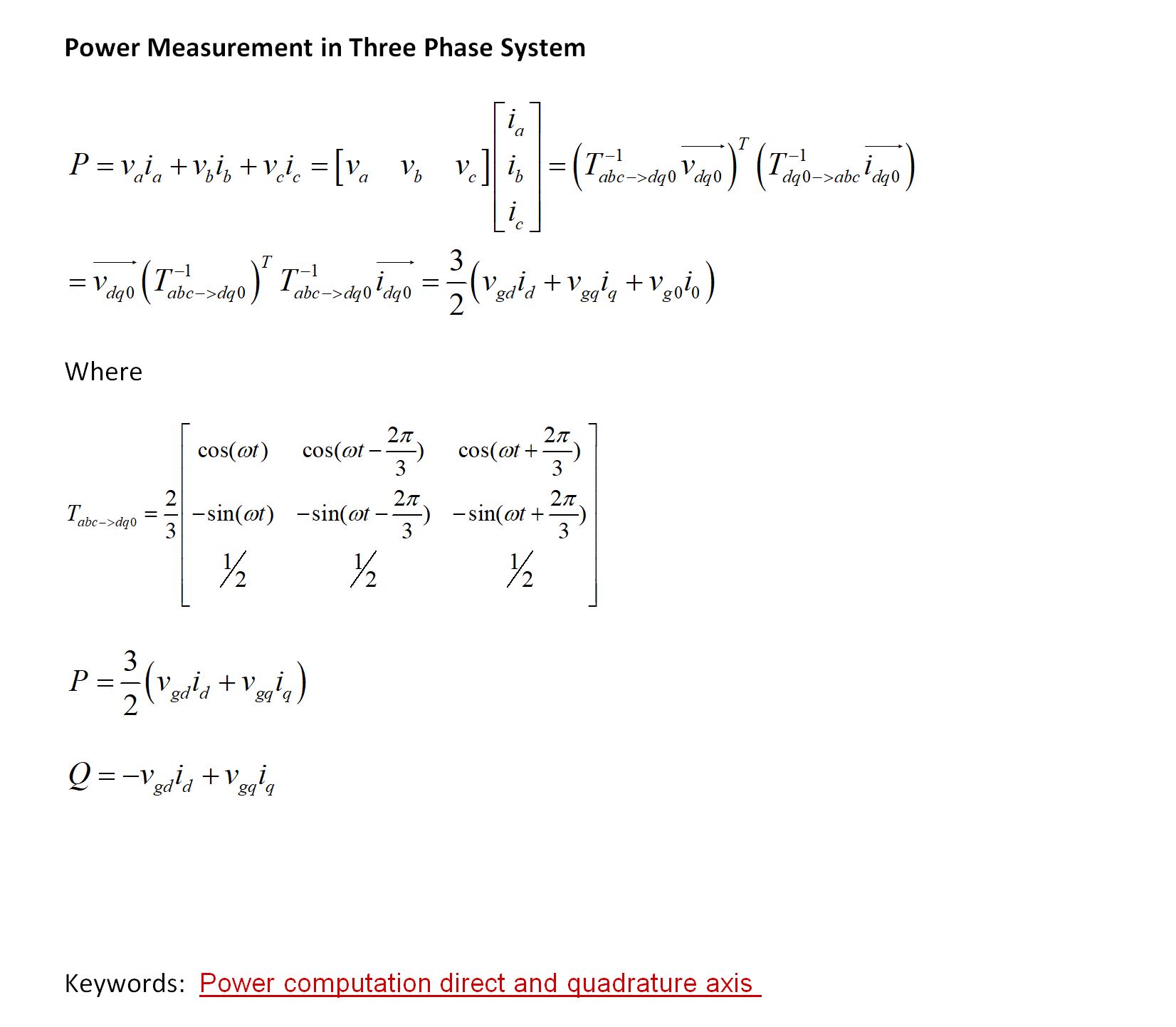
    Why don't you use the Vd and Iq values for power measurement it is relatively straight forward. 

  • Hi Manish and thanks for the reply.

    As I mentioned before, the problem is that I am using the code for measuring the power of a motor drive. So I don't have a voltage sensor nor an encoder (needed for park transformation).

    So my questions are still exist:

    " the applied voltage to the motor can be detected by using the PWM signals (e.g., volt_calc.h). The question is that can I use the "POWER_MEAS_SINE_ANALYZER" from Power Measurement Library for this purpose? In the guideline document, it is mentioned that the measured voltage should put into the function as the input. Can I use PWM signals due to the lack of voltage sensor?

    Where can I find a usage example of the POWER_MEAS_SINE_ANALYZER ? I have looked at "C:\ti\c2000\C2000Ware_DigitalPower_SDK_1_01_00_00\solutions\tidm_1000", however, the function "POWER_MEAS_SINE_ANALYZER_run" is not used in the code so I don't know how to put inputs to the function."

    Regards

  • Lio,

    So your real question is how to measure vd and vq of the motor without the real voltage sensor. 

    Yes you can use voltage calc for this function. 

    I will recommend using a transform to change valpha and vbeta that this module generates to DQ and then use the calculation above.

    You shall have Id and Iq already. 

    -Manish 

  • Manish,

    Thanks for the reply.

    Could you please let me know if there is a example file?

    regards

  • Lio,

    Sorry I do not have anything as a ready example, you may have to code and try.. Here are some snippets I have used on other projects,

        TINV_activePower = (TINV_vGrid_dq0_pos.d * TINV_iInv_dq0_pos.d +
                            TINV_vGrid_dq0_pos.q * TINV_iInv_dq0_pos.q) *
                            TINV_VGRID_MAX_SENSE_VOLTS * TINV_IGRID_MAX_SENSE_AMPS * (3.0f/2.0f);
        TINV_reactivePower = ( TINV_vGrid_dq0_pos.d * TINV_iInv_dq0_pos.q -
                             TINV_vGrid_dq0_pos.q * TINV_iInv_dq0_pos.d) *
                            TINV_VGRID_MAX_SENSE_VOLTS * TINV_IGRID_MAX_SENSE_AMPS * (3.0f/2.0f);

    Once you have Va,vb and Vc you can also use powerAnalyzer

        //
        // Calculate RMS input voltage and input frequency
        //
        TINV_sine_mains_A.v = TINV_vGrid_A_sensed_pu;
        TINV_sine_mains_B.v = TINV_vGrid_B_sensed_pu;
        TINV_sine_mains_C.v = TINV_vGrid_C_sensed_pu;
    
    
        TINV_sine_mains_A.i = TINV_iInv_A_sensed_pu;
        TINV_sine_mains_B.i = TINV_iInv_B_sensed_pu;
        TINV_sine_mains_C.i = TINV_iInv_C_sensed_pu;
    
        POWER_MEAS_SINE_ANALYZER_run(&TINV_sine_mains_A);
        POWER_MEAS_SINE_ANALYZER_run(&TINV_sine_mains_B);
        POWER_MEAS_SINE_ANALYZER_run(&TINV_sine_mains_C);
    
        TINV_iGridRms_A_sensed_Amps = TINV_sine_mains_A.iRms * TINV_IGRID_MAX_SENSE_AMPS;
        TINV_vGridRms_A_sensed_Volts = TINV_sine_mains_A.vRms * TINV_VGRID_MAX_SENSE_VOLTS;
        TINV_powerRms_A_Watts = TINV_sine_mains_A.pRms * TINV_VGRID_MAX_SENSE_VOLTS *
                         TINV_IGRID_MAX_SENSE_AMPS;
    
        TINV_powerFactor_A = TINV_sine_mains_A.powerFactor;
        TINV_gridFreq_sensed_Hz = TINV_sine_mains_A.acFreqAvg;
    
        TINV_iGridRms_B_sensed_Amps = TINV_sine_mains_B.iRms * TINV_IGRID_MAX_SENSE_AMPS;
        TINV_vGridRms_B_sensed_Volts = TINV_sine_mains_B.vRms * TINV_VGRID_MAX_SENSE_VOLTS;
        TINV_powerRms_B_Watts = TINV_sine_mains_B.pRms * TINV_VGRID_MAX_SENSE_VOLTS *
                         TINV_IGRID_MAX_SENSE_AMPS;
    
        TINV_powerFactor_B = TINV_sine_mains_B.powerFactor;
    
        TINV_iGridRms_C_sensed_Amps = TINV_sine_mains_C.iRms * TINV_IGRID_MAX_SENSE_AMPS;
        TINV_vGridRms_C_sensed_Volts = TINV_sine_mains_C.vRms * TINV_VGRID_MAX_SENSE_VOLTS;
        TINV_powerRms_C_Watts  = TINV_sine_mains_C.pRms * TINV_VGRID_MAX_SENSE_VOLTS *
                         TINV_IGRID_MAX_SENSE_AMPS;
    
        TINV_powerFactor_C = TINV_sine_mains_C.powerFactor;
    

    -Manish 

  • Manish, 

    Thanks for the reply.

    As I mentioned, Idon't have the rotor position (angular angle) to use park transform for calculation of RMS value or the power.

    Manish Bhardwaj said:
    Once you have Va,vb and Vc you can also use powerAnalyzer

    Coming back to my main question, can I use the inverter PWM signals (e.g., duty cycles of switches and measured DC link voltage) in "powerAnalyzer" instead of measured voltages?

    Regards,

  • Lio,

    You can use the Va , Vb and Vc from the voltcalc module, the valpha and vbeta from vcalc will not be correct as you do not have the right angle. 

    You can then use that in powerAnalyzer, however, the best way to do it is to try it on your side, because we have not done it ourselves and any suggestion here does not have experimental backing. 

    -Manish 

  • Hi Manish,

    OK! I'm gonna do that by myself.

    Regards,

  • Manish,

    Would you please let me know if powerAnalyzer can work in a wide range of frequency (e.g., 0~100Hz) ? As I noticed, it needs the Max and min frequency of grid as the inputs. What if I choose min freq=0 and Max freq =100 ? 

    What does variable "jitterCount" do in the code? 

    Where can I find the technical background document (PDF) of powerAnalyzer that describes how this module works? There isn't any technical information of how this module works in the "Digital Power Library User's Guide".

    I need this wide range because as I said, I want to use powerAnalyzer in motor drive application and the frequency of the motor varies widely.

    Regards.

  • The power analyzer has those max and min to avoid noise from the AC L-N distorting the AC half detection and causing erroneous readings. If you have a clean Vac sense which you may have in case of motor it may work ok for a wide frequency as well, 

    Please understand this is unchartered territory for the module and expect some surprises.