This thread has been locked.

If you have a related question, please click the "Ask a related question" button in the top right corner. The newly created question will be automatically linked to this question.

TMDXIDDK379D: TI Design Drive PWM Modulation: Unipolar or Bipolar?

Part Number: TMDXIDDK379D
Other Parts Discussed in Thread: CONTROLSUITE,

I'm curious which PWM modulation technique is used in the various example projects provided by TI in the Control Suite:

controlSUITE\development_kits\TMDSIDDK_v2.0\IDDK_PM_Servo_F2837x_v2_00_00_00

and also in the Fast Current Library:

controlSUITE\libs\app_libs\motor_control\libs\FCL\v02_00_00_00\lib

As described in this TI blog post, there are many different possible PWM modulation techniques, each with pro's and cons:

https://e2e.ti.com/blogs_/b/industrial_strength/archive/2012/03/19/so-which-pwm-technique-is-best-part-1

  • Most of our examples use space vector modulation, and the one in FCL is a different method using common mode injection giving similar results.

  • Ramesh, the main info I'm after is understanding how much current ripple will be produced.  The blog post linked to above clearly differentiates unipolar vs bipolar in this regard (bipolar producing significantly more current ripple compared to unipolar).  It does not mention space vector modulation or common mode injection, so its hard for me to understand what effect those strategies would have on current ripple. 

    Also, my understanding of SVM was that it was more analogous to a commutation technique rather than a PWM modulation technique.  Additional clarification would be appreciated.

  • We use PWM techniques that use up-down counting approach where the current ripple is at twice the PWM frequency but with half the magnitude compared to that with up count method, which is good. The influence of higher harmonic frequency with reduced magnitude will produce the least distortion on generated torque.

    SVM does go by 60 degree sector like you see the similarity to commutation, but the intent is to identify the pulse width based on a weighted average of the proximity of the voltage vector at any given instant to the adjoining switching vectors. In a two level inverter, there are 6 active switching states that produce the voltage of one full ac cycle of 360 degree, and that is why this 60 deg factor is showing up. It is as good as a sinusoidal PWM except that the timing values loaded into the comparator is calculated differently.

    Hope it helps.

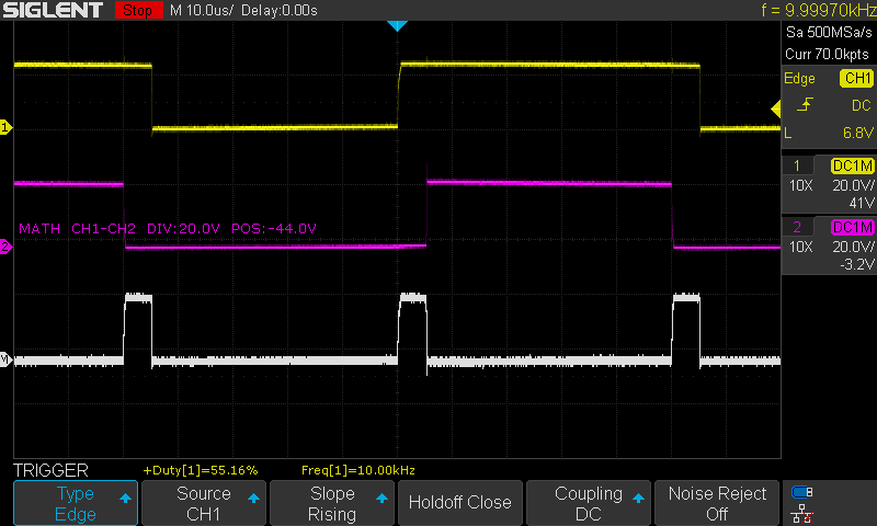
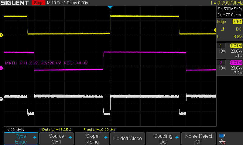
  • I ended up just probing my TMDXIDDK379D (PWM1H & PWM1L) to figure this out. Here is the scope trace for the following project:

    controlSUITE\development_kits\TMDSIDDK_v2.0\IDDK_PM_Servo_F2837x_v2_00_00_00 (build level 2)

    These traces are probed from the motor winding leads (yellow and pink) and the difference is taken to get phase-to-phase voltage (white)

    Here are some pictures showing unipolar vs bipolar schemes.

    As you can see, the scope trace looks the same as the bipolar scheme.

    In bipolar PWM, phase-to-phase voltage is either +bus voltage or -bus voltage, never zero.  Because I am observing periods of zero phase-to-phase voltage in my scope traces, it looks to me like the reference TI code utilizes unipolar PWM, which is the desired PWM modulation strategy for my application.