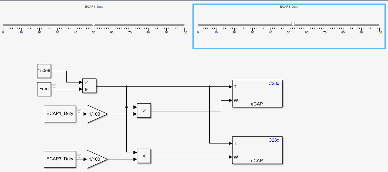
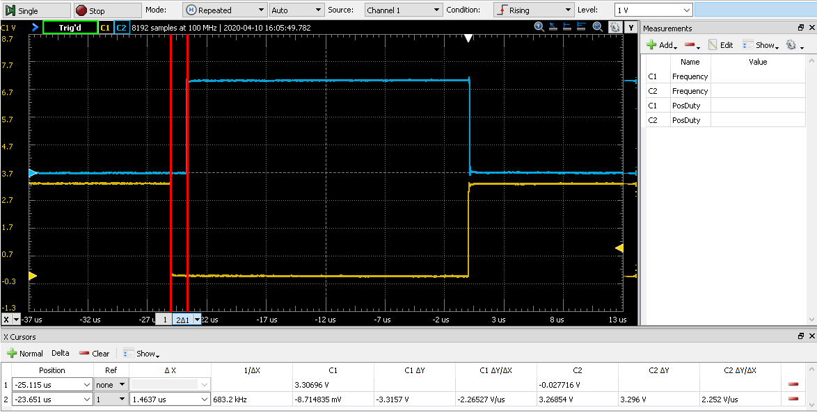
I need a pair of complementary PWM signals using 2 eCAP pins. Each eCAP pin is attached to an IGBT. The pair of complementary PWM signals needs to have dead band protection in order to prevent shoot-thru faults on the totem pole switch configuration. Unfortunately the dead band submodule is not included with the eCAP module. Another post recommended using the sync chain and the compare values to create a dead band between the complementary pair. I've developed an example application using Simulink Code Generation. I'm operating at 20kHz at a 50% duty cycle. With respect to the compare register, I understand if one of the complementary pairs has a slightly different duty cycle I effectively add a small amount of dead band. However, then I end up with the attached result which only inserts rising edge dead band due to the Up count type for the modulation. If I synced and phase shifted one of the PWM channels with respect to the other I believe I'd be able to introduce both rising and falling edge dead band. From the Simulink environment I have not been able to phase shift eCAP modules. Is there an example CC Studio that shows how to phase shift (2) eCAP modules? Is there a better way to introduce dead band with eCAP?