This thread has been locked.

If you have a related question, please click the "Ask a related question" button in the top right corner. The newly created question will be automatically linked to this question.

TMDXIDDK379D: Circuit breakdown

Part Number: TMDXIDDK379D
Other Parts Discussed in Thread: TMS320F28388D

Hello, This is jinsu park, South Korea.

I am testing TMDXIDDK379D with TMS320F28388D.

I refered to "Quick Response Control of PMSM Using Fast Current Loop".

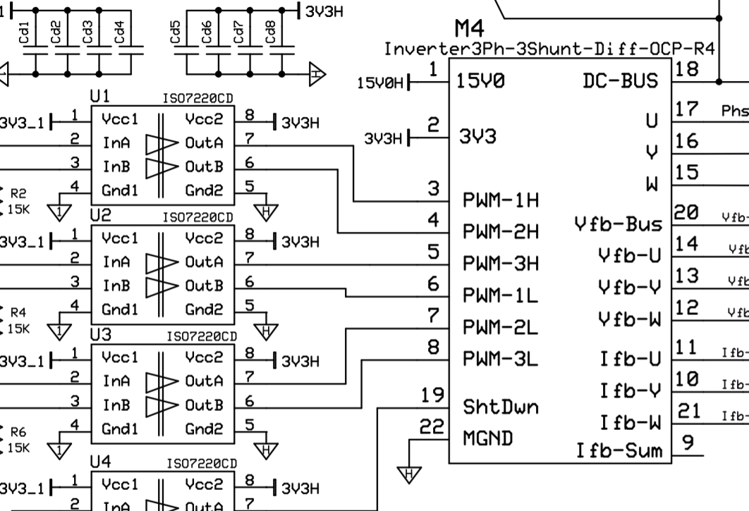
In 14 page, I observed two point (PWM-1H to 3H). and I made a mistake.

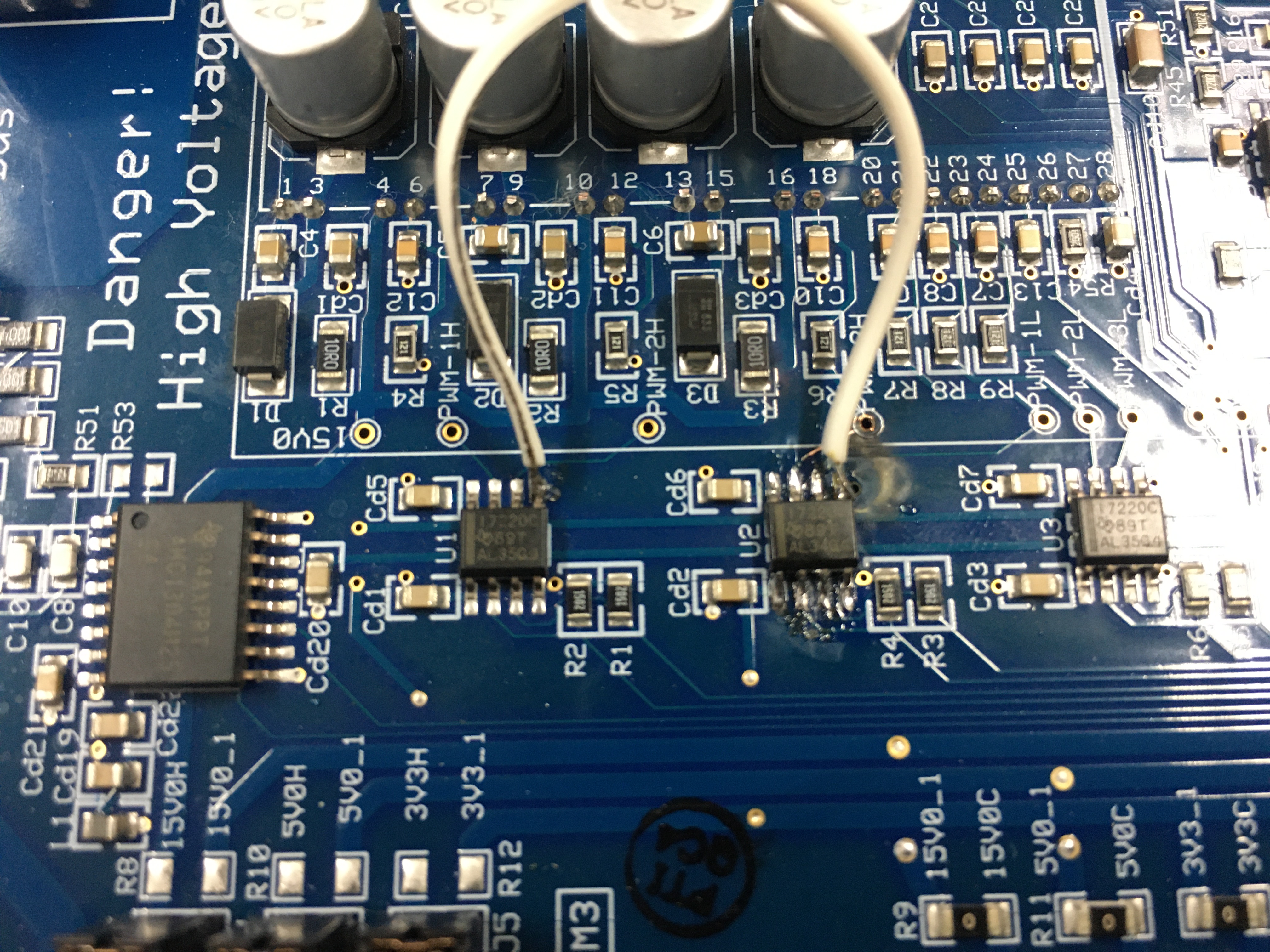
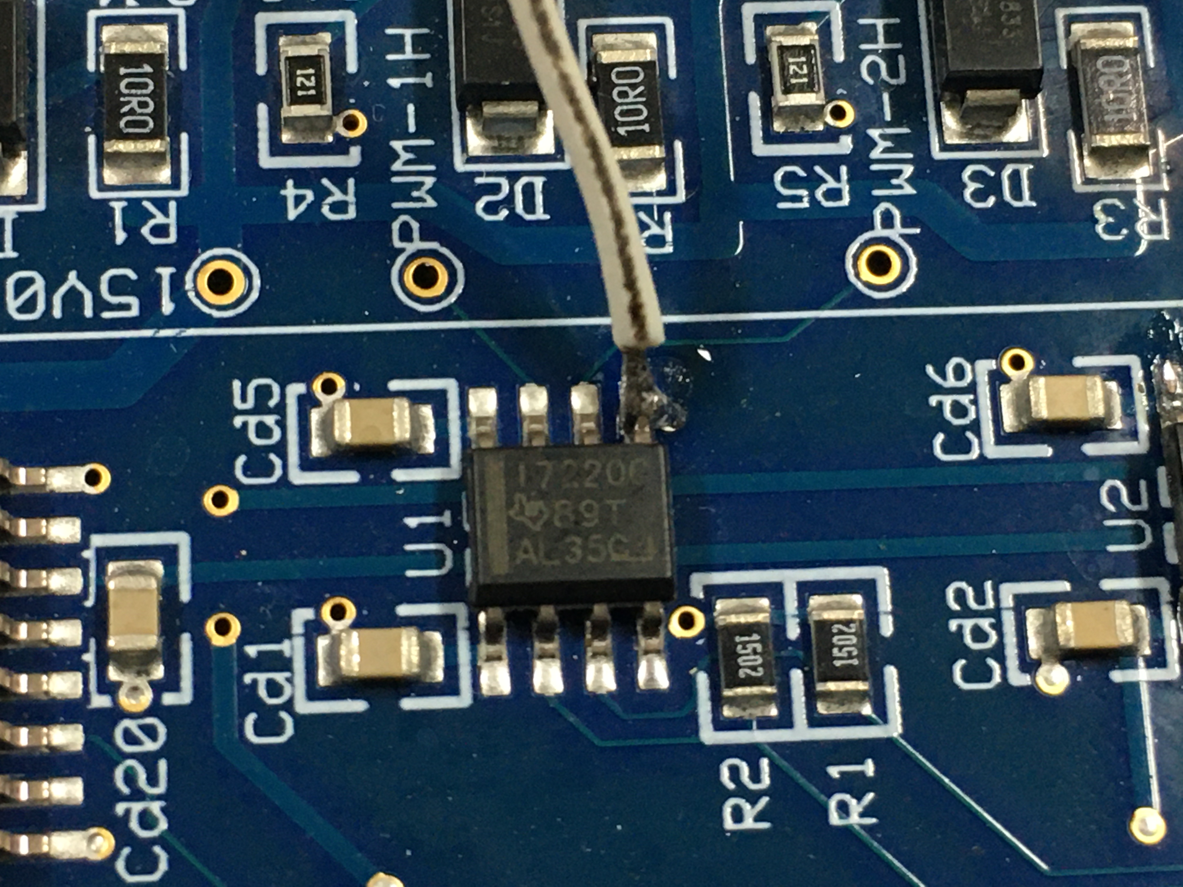
I point the two point(PWM-1H and PWM-3H) directly through oscilloscope. U2 was burned.

So, I want to repair the board. I live in Osan-city, South Korea. Please send me reply. Thank you.

  • Well, it is not clear why U2 would burn. If you connected the GND probes of the scope between the HOT and COLD sides, then the damage would have been bigger including your scope. Make sure you used isolated power supply until testing/ probing. Try replacing the damaged device, I dont know what else to say at this point. 

    I am closing the thread as a one off hardware issue for now. If you need further assistance here, reply back and we can continue.

  • Pin 5 of U2 (Gnd2) is burned.
    Since the pattern under pin 5 burned out and disappeared, I temporarily connected pin 5 of U2 and pin 5 of U1 with wires.
    The same Gnd2 on the circuit, so there seems to be no problem, but I want to get a definitive answer.
    We will check the PWM function using a 15V adapter to avoid circuit damage.
    After checking the PWM, we plan to connect the motor's UVW to the development board.
    And I used "ISO7220CD 89T AL34G4" as a replacement for U2. (Existing parts: "ISO7220CD 89T AL35G4")

  • Hmm... dont know what caused it. you may also want to make sure the inverter module (IPM) is not damaged during this. When you test the board again, you may want to use a low voltage dc to the dc link (say 10V or so, with power supply current limit to 0.2A or so). Check if you are able to see the inverter output voltage pulses matching to that of the input H side pulses.  Then gradually increase the voltage while continuing to monitor the output.  If you find any issue with this, you may need to replace the IPM as well.

  • Since the thread is inactive for so long without an update, we assume no further support is needed and so closing the thread.