This thread has been locked.

If you have a related question, please click the "Ask a related question" button in the top right corner. The newly created question will be automatically linked to this question.

TMS320F28034: ADCSOC trigger doesn't happen at the center of the center aligned PWM.

Part Number: TMS320F28034
Other Parts Discussed in Thread: TMS320F28035

Guys,

I need your help...

I am using TMS320F28035 MCU for a Motor Control Application.

In my implementation, I have 3 PWM A/B channels are configured and center aligned using up down counting mode. ADC is configured to trigger at the center of the center aligned PWMs. To verify it i have output the ADSSOCA signal on GPIO8. PWM is configured for carrier freq of 2.5KHz (T = 400us)

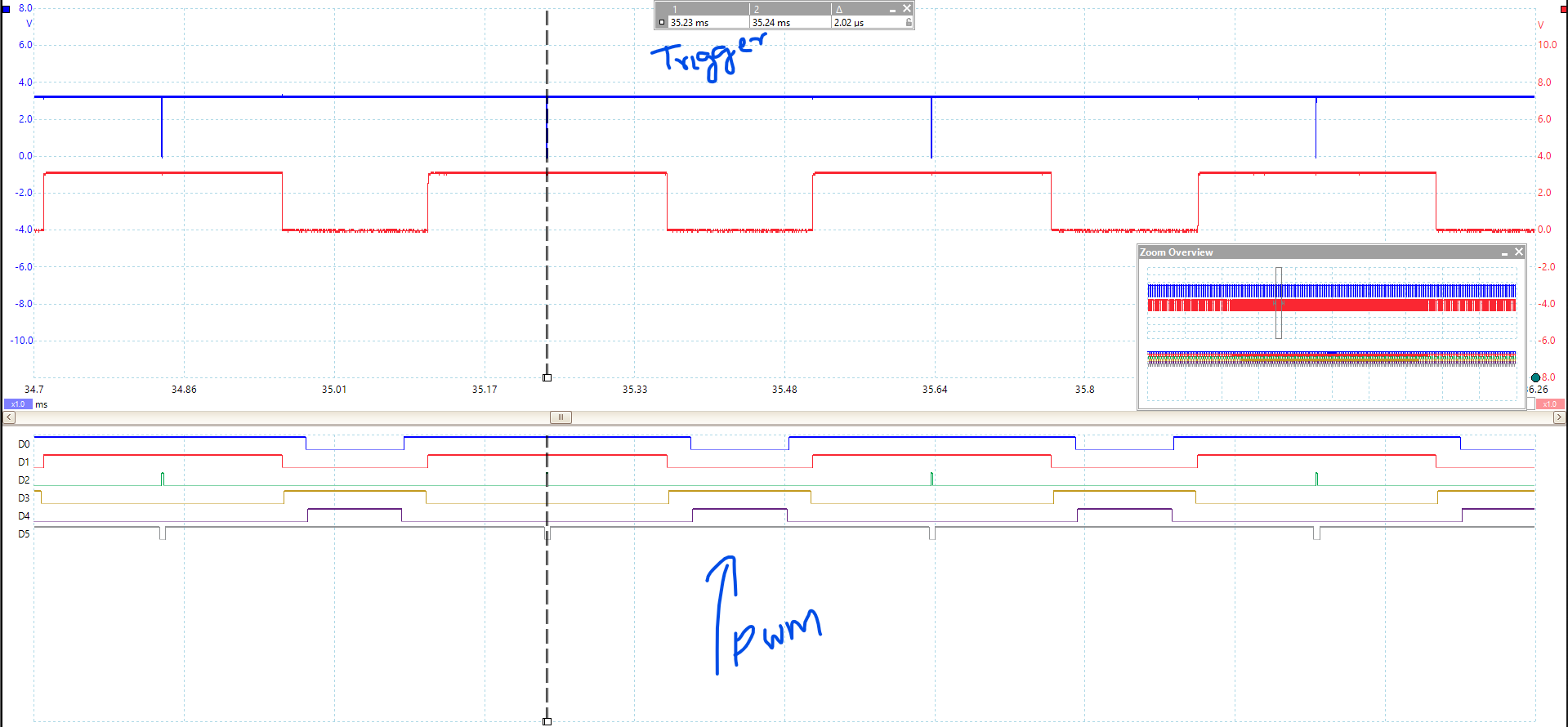
My observation : ADC trigger is not perfectly happening at the center of the PWM when PWM ON Time is 3-4us. Even for a 12 us ON time the ADC trigger is not center aligned. As the PWM width increase the trigger gets closer to the Center of the PWM. See the attached waveform Zoom Out & Zoom In. Channel 0,1,2 is the HIGH side (A) switching of the PWM 1,2,3. Signal in blue is the ADCSOCA trigger on GPIO8(Configured to output the SOC trigger instance)

In my application i want the ADC trigger to happen at the center starting from 3us wide PWM pulse. 

I have attached my PWM and ADC configuration files for reference.

I would appreciate someone can help me out with this.

//****************************************************************************
//  Function Name:  ADC_init
//      returns:    void
//      arg1:       void
//      Description:    Function needs to be called during board
//  initialization, in order to configure the ADC operation on the device.
//
//****************************************************************************
adcSetup_e ADC_init(void)
{
    AdcOffsetSelfCal();
    // Zero out the internal trim value.  This was a source of persistent
    // error.
    EALLOW;
    // Testing accuracy.
    AdcRegs.ADCOFFTRIM.all = 0x0000;
    EDIS;

    
	ADC_MACRO_INIT(m_ADC_chSelStd, m_ADC_trigSel, ACQPS)
    EALLOW;

    /* Set up Event Trigger with period enable for Time-base of EPWM1 */
    EPwm1Regs.ETSEL.bit.SOCAEN          = 1;    // Enable SOCA
    EPwm1Regs.ETSEL.bit.SOCASEL         = 1;    // Set to trigger on PWM prd counter = 0
    EPwm1Regs.ETPS.bit.SOCAPRD          = 1;    // Generate SOCA on the 1st event
    EPwm1Regs.ETCLR.bit.SOCA            = 1;    // Clear SOCA flag


    // Enable CNT_zero interrupt using EPWM1 Time-base
    EPwm1Regs.ETSEL.bit.INTEN           = 1;            // Enable EPWM1INT generation
    EPwm1Regs.ETSEL.bit.INTSEL          = ET_CTR_ZERO;  // Enable interrupt CNT_zero event
    EPwm1Regs.ETPS.bit.INTPRD           = ET_1ST;       // Generate interrupt on the 1st event
    EPwm1Regs.ETCLR.bit.INT             = 1;            // Enable more interrupts
    // PIE group 3
    PieCtrlRegs.PIEIER3.bit.INTx1       = 1;    //EPWM1_INT
#endif

    // Testing accuracy.
    AdcRegs.ADCOFFTRIM.all = 0x0000;
    EDIS;

    return m_ADC_channelConfig;
}
PWM_Config.h

  • Hi Amjad,

    Your captures appear to taken from multi channel logic analyzer, what bandwidth? Also GPIO pulse may not be exactly center position for narrow PWM pulses depending on bus arbitration timing, interrupts and trigger settings. Pulse position may not be revealing the entire truth for zoom outs! Yet zoom in refines the discrete timing of pulse position in any capture.

    You may be able to delay SOC trigger, check the technical resource manual for your MCU.  

  • Thanks a lot for the reply,

    I have a PICOscope doing sampling at 2Gs/s. 

    For your comment on GPIO pulse, if it's not outputting exact position as the ADCSOCA trigger then I would expect it to be showing delayed behavior instead of preemptive.

    I am unable to find a way to delay the ADCSOCA trigger in the MCU datasheet. I have worked on other manufacturer's MCU and FPGA where I did that easily.

    Thanks
    Amjad

  • Amjad,

    it looks like you have configured your ADC SOC pulse to happen in the middle of a PWM 'low time', is that correct?

    Are you adjusting the CMPA value? If so when are you loading it, if you load it halfway through your PWM period it may skew your high or low times. Making it look like your pulse isn't in the middle of your PWM pulse. Additionally if you are implementing a variable frequency application something similar could happen.

    Regards,
    Cody  

  • Cody,

    Thanks for the reply. 

    My PWM & ADC configuration is something like this

    PWM Setting for Interrupt generation is at TBCTR = 0.

    // Enable CNT_zero interrupt using EPWM1 Time-base
        EPwm1Regs.ETSEL.bit.INTEN           = 1;            // Enable EPWM1INT generation
        EPwm1Regs.ETSEL.bit.INTSEL          = ET_CTR_ZERO;  // Enable interrupt CNT_zero event
        EPwm1Regs.ETPS.bit.INTPRD           = ET_1ST;       // Generate interrupt on the 1st event

    And new duty cycle values are loaded via shadow register at TBCTR = 0

    #define CMPCTL_INIT_STATE ( LOADAMODE_ZRO + \
                                LOADBMODE_ZRO + \
                                SHDWAMODE_SHADOW + \
                                SHDWBMODE_SHADOW )

    My application is a variable frequency Drive application, but I am not changing carrier frequency i.e. TBPRD is constant throughout the operation.

    Thanks

    Amjad

  • Amjad,

    are you changing CMPA? It looks like you have CMPA set to shadow load on CTR=0, is that correct? This means that if you change CMPA it will adjust the CMPA value before CAU_CLEAR happens. This will cause the pulse to not be in the exact middle of the high time anytime you update CMPA.

    If you want the SOC pulse to be in the middle of the PWM's high pulse try updating the CMPA value during the low pulse, which for your settings should be at CTR = PRD.


    Regards,
    Cody 

  • This thread will be closing due to inactivity.

    Regards,
    Cody 

  • Cody,

    I apologies for keeping this thread open for so long without any activity. 

    I still didn't get the center aligned to work for 3-4us pulses. 

    Due to the project timeline, i had to find a workaround for it.

    I want to keep this thread open for one week so that I can get back to it and work with the TI team to resolve it.

    Thanks

    Amjad

  • Amjad Masood91 said:
    For your comment on GPIO pulse, if it's not outputting exact position as the ADCSOCA trigger then I would expect it to be showing delayed behavior instead of preemptive.

    That remains debatable depending on how CPU bus arbitration is being handled. We stopped trying to capture current center of PWM periods since true RMS values fall just under 90°/-180° lag behind voltage. Perhaps trigger a one shot CPU timer to delay SOC or use CMP-D-D of last PWM generator to synchronize captures. Perhaps configure a DC to fault the faster short pulse OC conditions, CBC or OSHT. Point being 12 bit embedded  SAR ADC is being oversold to capture often extremely fast current transitions at the Nyquist rate.


  • OK! no problem. Please report back when you know more.

    Regards,
    Cody