This thread has been locked.

If you have a related question, please click the "Ask a related question" button in the top right corner. The newly created question will be automatically linked to this question.

LAUNCHXL-F28379D: Using ZPK format compansator for digital control

Part Number: LAUNCHXL-F28379D

Hello,

I'm designing a digitally controlled buck converter. I've read DCL user guide and application note SPRAAB3.

First of all, I've planned to use "DCL_runPI_C1" function for compansator. "float32_t DCL_runPI_C1(DCL_PI *p, float32_t rk, float32_t yk" returns me the compansated error signal...

However, after reading SPRAAB3, I noticed that I didn't take "sample and hold circuit effects","computational delay" and "zero order hold effect" . As I read SPRAAB3, they reduce phase margin of system. Therefore, I tried to implement methods described at application note of SPRAAB3.

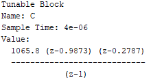
Let's consider that I've designed a series PI compansator at z domain by using sisotool and I want to us it at my ISR loop.

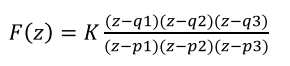
It has a form of below ZPK format.

I should call a function at ISR in order to use above compansator function. At DCL user guide, I couldn't understand how to use it because there is no "run" function for ZPK formated PI controller, which takes referrence and feedback value likeDCL_runPI_C1. 

There are some load functions like "Load the Series Form PI Controller from ZPK" as "DCL_loadSeriesPIasZPK" . However, I couldn't understand how to use it in my code.

My ISR is at below;

interrupt void CNTL_ISR(void)
{

yk = Vout_real; // Just information to me
uk = DCL_runPI_C1(&pi_cur, rk, yk); // Takes 52 cycle
EPwm1Regs.CMPA.bit.CMPA = period * uk; // Load New Duty Cycle

// Return from interrupt
EPwm3Regs.ETCLR.bit.INT=1; //Enable INT Flag to Enable Further Interrupts
PieCtrlRegs.PIEACK.all = PIEACK_GROUP3; // Acknowledge PIE group 3 to enable further interrupts
}

  • You can use the function "DCL_loadParallelPIasZPK" to load the zero frequency into the series PI_C1 controller. In the PI case you have only a gain, one configurable zero, and a fixed pole at the origin, so in the ZPK3 structure only K and z1 are relevant.

    The "DCL_loadParallelPIasZPK" function takes a ZPK3 description, computes the series PI gains, and loads them into the shadow parameter set (SPS) of the controller. To use it, you'll need to declare and initialize instances of the SPS and CSS structures in your code. You'll then call the "DCL_loadParallelPIasZPK" function with your controller configuration, and finally update the controller by calling "DCL_updatePI()" in your background loop. You will also have to set up the sample rate in the CSS so the DCL knows how to interpret the z1 frequency.

    Your ISR code does not need to change. You just need to add some declarations and code to your main file. Here is an example:

    // sample rate definitions
    #define SAMPLE_RATE 1000.0f
    #define SAMPLE_PERIOD 1.0f/SAMPLE_RATE

    // controller declarations
    DCL_PI pi = PI_DEFAULTS;;
    DCL_PI_SPS pi_sps = PI_SPS_DEFAULTS;
    DCL_CSS pi_css = DCL_CSS_DEFAULTS;
    DCL_ZPK3 zpk = ZPK3_DEFAULTS;

    void main(void)
    {

    // initialize controller structs
    pi.sps = &pi_sps;
    pi.css = &pi_css;
    DCL_SET_CONTROLLER_PERIOD(&pi, SAMPLE_PERIOD);

    // load controller parameters
    zpk.K = 12.3f; // example only
    zpk.z1 = 456.7f; // example only
    DCL_REQUEST_UPDATE(&pi);
    DCL_updatePI(&pi);
    ...

    You could also place a call to DCL_updatePI in your background loop if you intend to make manual adjustments to the controller parameters later. Section 2.4 in the DCL user's guide provides more information on this topic. I hope this helps.

    Regards,

    Richard

  • Hi Richard,

    Thank you for your clear explanation. It is really helpful. I'm new at c2000 and I kindly request you to review my work after your message. I explained my approach and why I needed ZPK3 format.

    APPROACH 1. I'm designing a digitally controlled buck converter (VMC). For control loop parameters, I used small signal models of converter and by using sisotool I designed a compansator in series form PI controller in s-domain. 

    Now, I need to reflect them to software.

    Then, I thought that both software side (DCL PI C1) and s-domain compensator (PI Compensator) side have same structure. Therefore, my s-domain designed compensator will show same performance at software also. My s-domain compensator bandwidth is 0.01*fsw. ISR loop interrupt frequency and mosfet switching frequency (fsw) are all same. As a result, I thought that I can directly use s-domain PI parameters, Kp and Ki can DIRECTLY be used at my digital DCL PI C1.

    Could you please comment on wrong phases of my approach?

    APPROACH 2. After reading SPRAAB3 application, I noticed that direct digital design approach shows better performance than my above approach. Because at above approach, I didn’t take the system delay which reduces my phase margin. Therefore, I digitalized my plant and again by using sisotool. I obtained a digital PI controller parameters as a format of below.


    Now, I need to reflect them to software.

    As I read from DCL user guide, “ZPK3” structure enables direct form compensators to be configured from specifications involving pole and zero frequencies.

    I thought that by using ZPK3 format I can directly use my z-domain compensator transfer function shown above and by multiplying it with error signal I could observe compensated signal...

    However, as I understood from your above exp., ZPK3 just helps me to form my real DCL PI C1 (Series PI function) and changes PI parameters according to format. I again will go on using run DCL_runPI_C1 function to use digital PI controller at my ISR. And therefore, that I previously used Kp and Ki parameters should be commented out because I will use ZPK3 format now in order to form series PI.

    Is my explanation correct?

    void main(void)

    {

       pi_cur.Kp = 10.0f;         //!< Proportional gain

       pi_cur.Ki = 1.0f;           //!< Integral gain

       pi_cur.i10 = 0.0f;         //!< I storage

       pi_cur.Umax = max_duty;     //!< Upper control saturation limit

       pi_cur.Umin = 0.0f;         //!< Lower control saturation limit

       pi_cur.i6 = 1.0f;           //!< Saturation storage

       pi_cur.i11 = 0.0f;         //!< I storage

       pi_cur.Imax = 1.0f;         //!< Upper integrator saturation limit

       pi_cur.Imin = 1.0f;         //!< Lower integrator saturation limit

    }

    a. The ZPK3 formated PI will show better performance (phase margin) than normal use of DCL PI C1 with Kp and Ki parameter etc. Is it correct?

    b. Is SAMPLE RATE same with my interrupt frequency or clock of CPU or control loop bandwidth frequency?

    c. I couldn’t see that you inserted “DCL_loadParallelPIasZPK” function at your above code. By the way, DCL PI C1 is series form PI, why you didn’t offer “DCL_loadSeriesPIasZPK”.

    I'm sorry for taking your time on same topic.

  • Approach 1: It's not that simple, unfortunately. The gains will be different because you have to take sampling into account. You cannot simply apply your continuous PI controller gains to a discrete time controller.


    Approach 2: Your target design has two zeros, so you cannot implement this with a PI controller. As I explained, the PI has a single zero, so in terms of the ZPK3 structure, only K and z1 are relevant (z2 is ignored). If you want to implement this design I suggest you change to a DF22 compensator. You can then map your ZPK3 description across using "DCL_loadDF22asZPK".

    a. The ZPK3 formated PI will show better performance (phase margin) than normal use of DCL PI C1 with Kp and Ki parameter etc. Is it correct?

    --> I'm not sure what you mean by 'normal use'. If you load Kp & Ki from a ZPK3 structure into a PI controller the performance you get depends on your selection of the zero frequency and the gain.

    b. Is SAMPLE RATE same with my interrupt frequency or clock of CPU or control loop bandwidth frequency?

    --> SAMPLE_PERIOD (in my previous example) is the update period of your controller. It's the reciprocal of the rate at which you run the PI controller.

    c. I couldn’t see that you inserted “DCL_loadParallelPIasZPK” function at your above code. By the way, DCL PI C1 is series form PI, why you didn’t offer “DCL_loadSeriesPIasZPK”.

    --> You are right. Sorry, I missed that. In my example you'd replace those lines which set up the Kp & Ki gains with a call to "DCL_loadSeriesPIasZPK".


    Regards,

    Richard

  • Richard,

    I got all points thank you.

  • Dear Richard,

    I tried to convert my DCL PI C1 to zpk formated PI a below, however I got errors could you please review?

    1. I just commented out Kp and Ki lines, and inserted DCL_loadSeriesPIasZPK. Because I still want to use Umax and Umin etc.. Could you please correct me also?

    2.How can I solve the errors?

    My code is below, it is cleared by deleting some parts.


    #include "F28x_Project.h"
    #include "DCLF32.h"

    //
    //=====================================
    // Function Protoypes
    //

    interrupt void CNTL_ISR(void); //EPWM 3 is used to trigger CNTL ISR when TBCTR=CMPB


    //===================================== DCL =====================================//
    // Sampling Rate Definitions for ZPK Formated PI Controller
    //
    #define SAMPLE_RATE 5000.0f;
    #define SAMPLE_PERIOD 1.0f/SAMPLE_RATE; //ZPK Format, C2D Transformation Sampling Time

    DCL_PI pi_cur = PI_DEFAULTS; //It is to be called at ISR


    DCL_PI_SPS pi_sps_cur = PI_SPS_DEFAULTS;
    DCL_CSS pi_css_cur = DCL_CSS_DEFAULTS;
    DCL_ZPK3 zpk_cur = ZPK3_DEFAULTS;

    float32_t uk; // OUTPUT of Current loop PI Control Output
    float32_t rk = 15.0f; // REFERRENCE of Current loop PI Control Reference
    float32_t yk; // FEEDBACK of Current loop PI Control Reference


    void main(void)
    {

    //
    //=====================================
    // DCL Initialize Controller Structs
    //

    pi_cur.sps = &pi_sps_cur;
    pi_cur.css = &pi_css_cur;
    DCL_SET_CONTROLLER_PERIOD(&pi_cur,SAMPLE_PERIOD);

    //
    //=====================================
    // DCL control variables
    //
    //pi_cur.Kp = 10.0f; //!< Proportional gain (Commented because ZPK format to be used)
    //pi_cur.Ki = 1.0f; //!< Integral gain (Commented because ZPK format to be used)
    DCL_loadSeriesPIasZPK(&pi_cur,&zpk_cur); //Loads the SPS coefficients to form series form PI controller
    zpk_cur.K = 10.0f; // example only
    zpk_cur.z1 = 1.0f; // example only
    pi_cur.i10 = 0.0f; //!< I storage
    pi_cur.Umax = max_duty; //!< Upper control saturation limit
    pi_cur.Umin = 0.0f; //!< Lower control saturation limit
    pi_cur.i6 = 1.0f; //!< Saturation storage
    pi_cur.i11 = 0.0f; //!< I storage
    pi_cur.Imax = 1.0f; //!< Upper integrator saturation limit
    pi_cur.Imin = 1.0f; //!< Lower integrator saturation limit
    DCL_REQUEST_UPDATE(&pi_cur);
    DCL_updatePI(&pi_cur);

    do {

    GpioDataRegs.GPADAT.bit.GPIO31 = 0; // Turn on LED
    DELAY_US(1000*500);

    } while(1);

    }

    interrupt void CNTL_ISR(void)
    {
    uk = DCL_runPI_C1(&pi_cur, rk, yk); // Takes 52 cycle
    EPwm1Regs.CMPA.bit.CMPA = period * uk; // Load New Duty Cycle

    // Return from interrupt
    EPwm3Regs.ETCLR.bit.INT=1; //Enable INT Flag to Enable Further Interrupts
    PieCtrlRegs.PIEACK.all = PIEACK_GROUP3; // Acknowledge PIE group 3 to enable further interrupts
    }

    // end of file

  • You need to remove the semi-colons from the two #defines.  You should have:

    #define SAMPLE_RATE 5000.0f
    #define SAMPLE_PERIOD 1.0f/SAMPLE_RATE

    I can't see anything obvious in the rest of the code.

    Regards,

    Richard

  • Dear Richard,

    Thank you for your answer.

    I removed semicoloumns at above code but I got now following errros. I generally cannot understand where the error is on usin CSS.

  • Some DCL functions contain basic error handling to ensure the parameters being loaded make sense.  One of these is the DCL_loadSeriesPIasZPK function you are using.

    Error handling is globally enabled in the header file DCL.h.  In DCL v3.3 it's line 225 of this file:

    #define DCL_ERROR_HANDLING_ENABLED

    If you comment out this line, all error checking is turned off and your code will build.  The reason you are getting this message is because error checking is enabled and you have not added the error handler file to your project, so the compiler can't find the error function.  It's just that the source file "DCL_error.c" needs to be added to your CCS project.

    So, you can either

     - comment out line 225 in DCL.h, or

     - add DCL_error.c to your project.

    Regards,

    Richard

  • Dear Richard,

    I appreciated your detailed and clear explanations. My problem is solved.

    Thank you for your effort.

  • You are welcome!  Glad to know it's working.

    Regards,

    Richard