This thread has been locked.

If you have a related question, please click the "Ask a related question" button in the top right corner. The newly created question will be automatically linked to this question.

TMS320F28069: Instaspin current feedback off at high speed?

Part Number: TMS320F28069
Other Parts Discussed in Thread: BOOSTXL-DRV8320RS, INA240
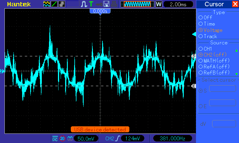
I'm trying to drive a BLDC fan motor using InstaSpin-FOC.  It seems to mostly work, but at high speed and torque I get waveforms like in the above scope capture which are pinched at the bottom.  Is that normal, or what can I do about it?

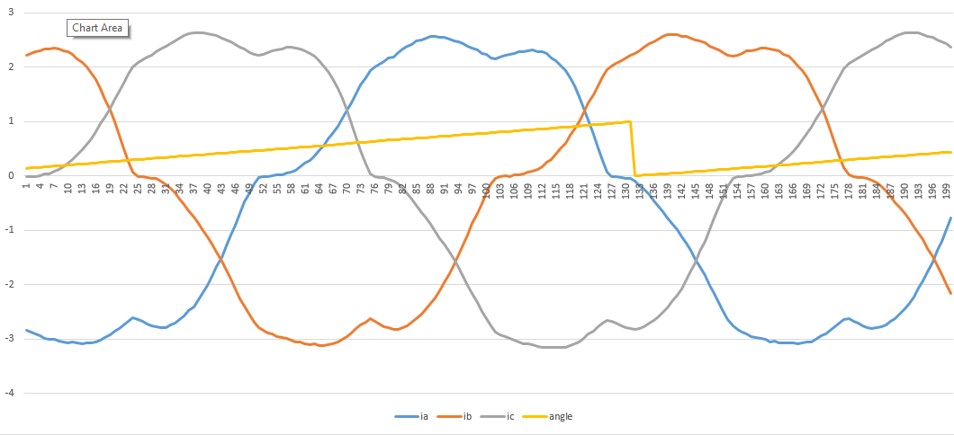
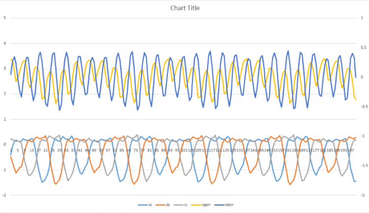
Then also, and probably more importantly, the other plot shows how at high speed (torque doesn't matter) I get a large offset in the reported current feedback.  I have about 0.25A in the positive and 1.5A in the negative.  Putting a current clamp on the phase to the motor I see at most a 20% offset from zero, something like 0.5A one way and 0.6A the other.

I'm sure I haven't provided enough information, so let me know what you need and I'll post it.  Thanks!

  • You might try something as below.

    1. Calibrate the current and voltage sensing circuit to improve the sampling resolution.

    2. Tune the Gains of the speed controller.

    3. Identify the motor parameters of each board and motor separately. 

    3. Check if there is an overflow of current sensing.

  • Thank you for the response.

    Your suggestions seems like they might help the pinched waveform problem, not so much the offset current feedback at high speed, is that right?

    1. I have spent a good amount of time calibrating the current feedback.  It tracks pretty well at low speed.  I haven't looked at the voltage in a while so I will double check that.

    2. I am using my own speed controller, but I don't think it should affect the current feedback in this way.  Maybe the gains of the current loop?  But I've done a lot of playing with that and this is the best I can get it to look.

    3.I am using somewhat generic motor parameters since this is intended to work with a couple of different motors and be interchangeable.   Again can't see that affecting the offset current feedback.

    4. I have seen the current feedback go much higher than what is in the plot above so I don't think it's overflowing, unless there is an accumulator somewhere in the code that is somehow related to motor speed.

    Thanks again.

  • Are there any other suggestions out there?

  • The waveform should be normal if you make sure that the current & voltage offset and sensing signals are well and the motor parameters are identified correctly. 1. You might check what's the USER_MAX_VS_MAG_PU in user.h, and if the gMotorVars.Vs is equal to the USER_MAX_VS_MAG_PU when the motor is running with high speed.

    2. What's the high speed (electrical frequency) you tested? What's the USER_VOLTAGE_FILTER_POLE_Hz? Do you have the BEMF data of the motor from its manufacturer? 

  • Thanks Yanming.

    The current and voltage offsets are measured during enable with Flag_enableOffsetcalc == true.

    The current sensing signal seems ok at low speed, just not high speed.  I haven't looked closely at the voltage feedback signals, but the bus voltage is reporting correctly which is affected by the same scalars, right?

    1. USER_MAX_VS_MAG_PU is set to 1.15.  On one run that was going about 80% of our max speed of 7000rpm the Vs was between 0.7955 and 0.8233.  I can do that again at 100% speed to see if it gets up to 1.15.

    2. We're running at 7000rpm on a 8 poll (4 poll pair) motor, so the electrical frequency ought to be 466Hz I believe.  The USER_VOLTAGE_FILTER_POLE_Hz is set to 970.78.  I just spent some time talking to our EE who says the latest rev board took that filter out all together so is suggesting I turn up the pole number to something very large.  Do you agree?  I need to confirm but I have a datasheet that says the Back EMF is 29.4V / krpm.

    I will add another plot that shows our current feedback looking ok at high torque / low speed.

  • Hi Jacob,

    I have asked about the same inflections occurring in the current and received no logical explanation. Off hand your above capture appears as if a phase margin error exists in PWM duty cycle being out of synchronization with one or both Clarke inputs.

    That seemingly occurs from fact inductive current lags 90° behind VEMF and must be compensated for. Since FAST module is so secretive "little to no technical brief" it would seem it (TI example code) does not compensate for the inductive current lag causing distorted sine waves. One option is to simulate the BLDC via Matlab models of FAST estimator, Clarke/Park transforms in order to reveal or determine reason for current distortion. Perhaps TI has these models available for Matlab simulation of the older MCU classes. 

    Alternatively you can experiment with SOC triggers and interrupt decimation times to see if that improves things.   

  • Hi Jacob,

    Yes, it seems like the 466Hz electrical frequency is not too high for InstaSPIN. The over-modulation and current reconstruction are not implemented since the voltage vector magnitude is lower than _IQ(1.0), so the current sensing may not be the issue for the high speed of your motor. 

    1. You might change the voltage sensing circuit and ensure the voltage filter pole frequency is between 600Hz and 800Hz which should be fine for your motor.

    2. There is a software filter for the speed estimate, which is currently set to 100 rad/s (USER_SPEED_POLE_rps) by default. You might change that the value to 300 rad/s, even try 500 rad/s or 1000 rad/s.

  • Yanming Luo said:
    1. You might change the voltage sensing circuit and ensure the voltage filter pole frequency is between 600Hz and 800Hz which should be fine for your motor.

    Yet how do you explain the same odd current distortion below capture occurs at much lower speeds 150Hz via new SDK and BoostXl-drv8320rs default filer pole settings? The inductive phase current angle is clearly not in phase with PWM drive causing notched current distortion. Clarke is obviously problematic since motor control suite days. Using PWM module to SOC trigger Ia,Ib,Ic samples seemingly is occurring after the fact, missing RMS peaks and creating notched offsets. It strikes me odd Clarke emf (Va,Vb,Vc) has same SOC trigger source as current (Ia,Ib,Ic) when electrical theory states inductive current lags voltage by 90°. It would seem the SW has timing issues that must be addressed well before customers can have precision results. 

  • OK, so our EE removed some filtering on the op amp for the current feedback which had caused a reduced gain at higher currents.  Between that and whatever other fiddling I've been doing in the code the offset on the current feedback has gone away.  The EE says he can't see how removing that filtering would induce an offset, but I can't see how my code changes would either.  If it makes sense to you please explain.

    So now I'm left with the crummy wave form to fix and it's still an issue.  I've moved to another motor and I'll try posting the latest waveform for you to look at here soon.

    I believe the only difference between our circuit and the reference circuit is we have a higher filter.

  • Jacob Lewis said:
    whatever other fiddling I've been doing in the code the offset on the current feedback has gone away.

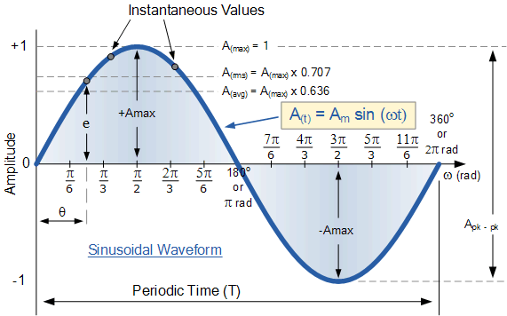
    Do you mean the notches in the sine wave and is not that the actual current recreation events occurring? If you want to get a better perspective on how current lags behind voltage, this tutorial link may help. The SDK also triggers SOC via last generator CMP-D but it still may have missed the +Amax at 90° and hit either one Instantaneous values. Yes it is a generator in tutorial but the very same magnetic events should occur for PM motors. The BLDC can cause rotor position issues if the sine is notched near +Amax.

    Perhaps test phases disconnected from PCB, scope any two via probe/gnd then rotate shaft by hand. If it makes a pure sine wave the 6 angles should be easy for FAST to observe. Otherwise 7k RPM might be a reach for SVPWM regardless of FAST claims to spin any motor but it does. What is the top speed after filter change? The measured speed is relative to rotor frequency and you must use a laser gun to verify rotor speed is indeed what simple math predicts.

    https://www.allaboutcircuits.com/textbook/alternating-current/chpt-3/ac-inductor-circuits/

    Please do post your after results capture, current amp filter capacitance can roll off or delay the phase angle in/out of the RMS regions. The BoostXL-Drv8320Rs had extensive PGA filtering via (TMS280x49c) and capture I posted above was the default filter pole settings. So if SOC triggers for EMF and current occur together how is the current creation 90° offset from emf events?


  • Hey guys, just wanted to let you know that I've been experimenting with a different motor that appears to be behaving better, but I haven't been able to load it like I had been doing the first motor.  I should be back to the previous system tomorrow and will report back results from further tests.

    Thanks.

  • Sanity check question: if I set the Iq_ref to 1A, am I going to see 1A output on the phase peak to peak, or is that from 0 to peak?  The scope catpure below is with Iq_ref set to 1A, and the output is 1A peak to peak, is that right?

  • Here is my latest.  You see the phase current has a kind of pointy bottom side, and there's a strange right hand shoulder on the upper side.

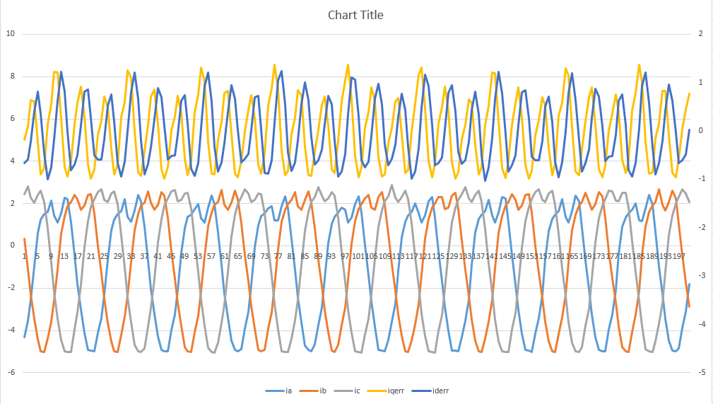
    Then in the plot below you can see there's still an offset in the phase current feedbacks, and a messy top to them.  Is that normal?

    I'm really confused by the current feedback scaling.  When I run the calc from section 5.2.1 in the manual I think USER_ADC_FULL_SCALE_CURRENT_A should be set to 21.2.  But then my output is 1A peak to peak when Iq_ref is 1, and I think it's supposed to be 1A zero to peak, right?  Also the motor doesn't run as well with that value.  So I set it to 10.6, the motor works better, and I get 1A output zero to peak. 

    For the equation my values are:

    • Rshunt = 0.05
    • Rfbk = 30,100
    • Rin = 10,000

    So for Vout of 3.3 Iin should be (3.3-1.65) / Rshunt * Rin/Rfbk = 10.6.  That's in the positive direction, so you double to get the full range and it should be 21.2, right?

  • Hi Jacob,

    You can get a higher phase current accordingly if the reference torque current is set to a higher value, but there is not a constant proportion between these two values.

    The top waveform captured by the oscilloscope seems good, but the feedback signals in the bottom figure are not correct. It's very strange, I don't think the phase current waveform of the motor will be so good as the top waveform if the controller uses the bottom feedback signals. Do you have any chance to use DAC or PWMDAC to check the feedback signals?

    The USER_ADC_FULL_SCALE_CURRENT_A should be the full range of the ADC, so it is 3.3/Rshun/(Rfbk/Rin)=21.9269(A).

  • Jacob Lewis said:
    Then in the plot below you can see there's still an offset in the phase current feedbacks, and a messy top to them.  Is that normal?

    That depends on what the motor feed back looks like when you spin it by other means, does it produce symmetric waves? But yea agree it looks like the 3rd harmonic is not being detected or injected. NXP has nice Matlab informative as to 3rd harmonic benefits of AC current peak symmetric +/-AMax. Otherwise some kind of harmonic distortion seems to be present on newer motor. Have you tried another current monitor such as INA240 to verify if the the distortion is due to amplifier/shunt selection issues?

    You can attach INA240 vertical sub PCB placed directly above shunts via 2 gold plated pins formed outward and solder to edge of each shunt. The 240 does produce a very clean sinusoidal wave form and added bonus of PWM rejection. Perhaps even try one sub PCB just to compare the difference.


  • Hi Jacob,

    Any updates? Do you enable the current&voltage offset calibration? Or do the offset calibration and set the related numbers in the file of the user.h for each board separately? 

  • Hi Yanming, thanks for checking in. I had been typing up an update a couple days ago and then thought of one other thing to try. I tried it and it made no difference so no update there.  We did discover that the board I was using had old rev parts on it so that's what was messing up my scaling.  One mystery solved.  We got the drive working well enough for UL testing, but the mystery of those odd current feedback waveforms remain.  

    I do the current and voltage offset calibration with every enable of the drive.

    I am eventually going to try making a copy of the feedback values immediately after reading them so that I have a copy that should never get touched by Instaspin or anything else just to make sure that's really what I'm getting from the ADC.  That probably won't be for a while though so if you want to mark this thread closed for now you can.  I appreciate your help.

  • Great. Please let me know if you have any further questions. Thanks!