This thread has been locked.

If you have a related question, please click the "Ask a related question" button in the top right corner. The newly created question will be automatically linked to this question.

CCS: Technical problems about 28379d and three-phase inverter board bostxl-3phganinv!

Other Parts Discussed in Thread: BOOSTXL-3PHGANINV

Tool/software: Code Composer Studio

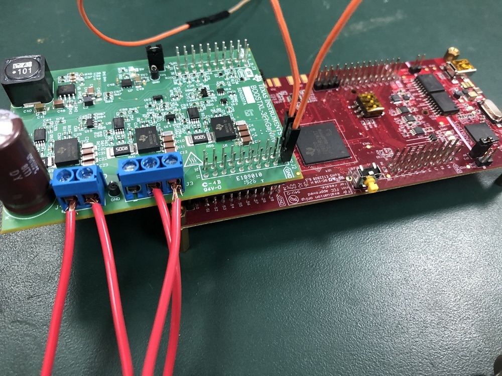
I have programmed SVPWM algorithm in 28379d, and pwm4-6 can output three pairs of complementary PWM waves, but after connecting with three-phase inverter version bostxl-3phganinv, DC input is 15V, but in three-phase output VA, VB, VC can not get any waveform.I just burned in the program in 283789d during the test, provided the bootxl-3phganinv board with PWM wave, then connected and powered up correctly according to the way in the instructions, but I did not carry out these steps in the instructions "2.4.2 set up bootxl-3phganinv.........". At the beginning, I'm still a little unclear. I look forward to your answer. Thank you.
  • You generate and feed PWMs into BOOSTXL-3PHGANINV (GaN inverter) but not able to see the output voltage, well, I have not come across this problem to exactly say where to look at. However, suggest to review the Gan inverter schematic and see if there is any active shutdown signal shutting down the inverter. 

  • Let us know if you were able to debug the issue?

  • This problem still hasn't been solved. I put 28379d into SVPWM algorithm, and then connect inverter board with 28379d correctly. Under 15-30V DC input, we can't get sine wave by measuring VA, VB and VC with oscilloscope.

  • Before burning the SVPWM algorithm to 28379d, after connecting with the inverter board, test that the corresponding pin on the inverter board can display PWM wave on the oscilloscope, but the sine wave can not be obtained in VA, VB and VC, and then I burn the routine of the dual motor on the inverter board, but also the waveform can not be obtained in VA, VB and VC. If you can, can you test this routine for me? It may be that I have some problems in operation. I look forward to your answer.

  • VA, VB and VC will be pulsed outputs representing a sine wave and not a clean sine wave.

    If you followed the instructions in the user guide, you should not run into this issue. Suggest to reveiw the schematic of the booster pack and see where the pulses dont translate to switching the inverter. 

  • Thank you for your reply. At present, I only have 28379d and boost xl-3phganinv in hand for the dual motor routine. I don't have a motor. I want to test whether the inverter can be completed. The sine wave can be detected by the oscilloscope. According to my current conditions, can I carry out this operation? Is the value of the phase current tested?

    Or according to the SVPWM program I wrote in 28379d, to test the inverter performance of boost xl-3phganjnv, in order to test the sine wave, can this be achieved?

  • I want to complete the inverter test, and in the oscilloscope output sine wave, whether to connect the load in VA, VB, VC? Then test the phase current?

  • Like i mentioned earlier, you will not see sine wave on VA, Vb and VC. What you see will be pulsed outputs whose widths vary according to the sine wave it is trying to output.

    You dont need a load to see these waveforms, without load, there is no inverter current and it is safe to operate the inverter.

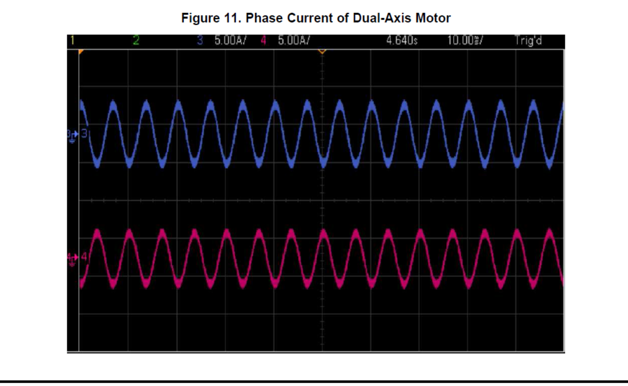
  • Thank you for your answer. I can see what you mean. I want to use 28379d and boost xl-3phganinv to realize the inverter function. The purpose is to observe the sine wave on the oscilloscope. You say VA, VB and VC can't see the sine wave. You should test the phase current of the load to get the sine wave. In a word, I want to realize AC to DC and finally get sine wave in oscilloscope.I am now studying the dual motor routine based on boost xl-3phganinv, according to the following figure (provided in the file tidude0):

    But I don't have the motor required by this routine, only the inverter board and 28379d, can I carry out this test? Or use another type of motor I have? Can this routine test sine wave? Please give me some advice, thank you very much.

  • If you review the schematic of BOOSTXL-3PHGANINV, you can notice that there is a low pass filtered output of VA, VB and VC. This will give sinusoidal output representing the output voltage. Hope it helps.