


Part Number: TMS320F28379D
Tool/software: Code Composer Studio
Hello everyone,
I am trying to integrate the DSP to my prototype PCB instead of using the mounted controller card. I am using the 176-pin version of the DSP. I have everything soldered now and I was trying to communicate using the JTAG without success. My question is: what are the minimum requirements for communicating with the DSP? Below is the list of what I have so far. Am I missing something?? Is there anything that I should particularly careful? Please, help me. I am completely stuck. I cannot do anything before this DSP turns on and communicate correctly.
- Connected ground pad at the center of DSP
- Connected all Vdd to +1.2V
- Connected all Vddio to +3.3V
- Connected VDDOSC like shown below.

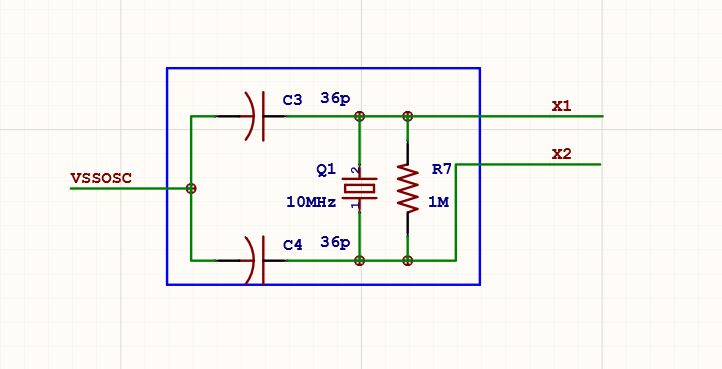
- Connected X1,X2 and VSSOSC as shown below.
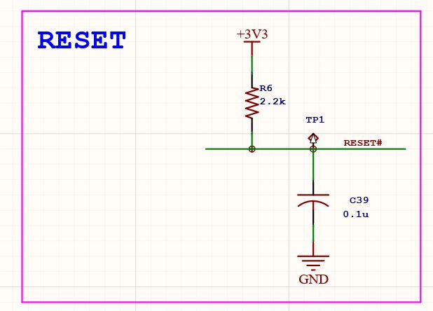
- Connected XRS like shown below. Note: The signal RESET# is equal to XRS
- Connected VRGENZ to Vddio (+3.3V).
- The pins TCK, TDI, TMS goes directly to the connector to the JTAG communication.
- Pin TDO in series with a 4.7k resistor and then goes to JTAG connector
- Pin TRST with 2.2k pull down resistor.
- Pins FLT1 and FLT2 unconnected
- PIn Vdd3vfl connected to 3.3V.
- GPIO 84 connected to ground with a 2.2k pull-down resistor.
- GPIO 72 connected to 3.3V with a 820 Ohms pull-up resistor.
I am using decoupling capacitors as recommended in the manual. Below is the message that I am getting from the code composer when trying to communicate via JTAG.

In the JTAG (TMS320-XDS100V3) connector I am not connecting: T_EMU0, T_EMU1, T_RTCK, T_DIS and the pin TVD is connected to 3.3V.
I know that the problem is not with the JTAG emulator since I have already tested it.
I really appreciate any help!
Thanks
Renato
