Part Number: TMS320F28388S
Hi Expert,
My customer are working on F28388 I2C for Epprom, they face issue that read the wrong value.
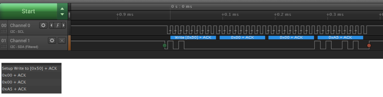
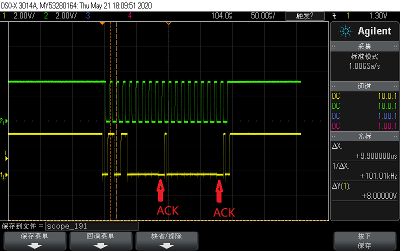
They write the data 0xa5 to address 0x00 as below, it seem the waveform are correct.
1. waveform of high address 0x00.

2. waveform of lowaddress 0x00.
3. waveform of the data 0xa5 that write to EEPROM.
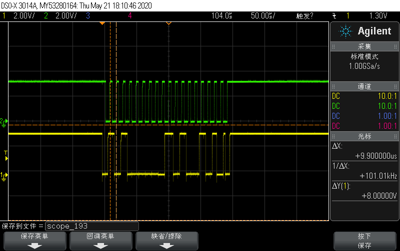
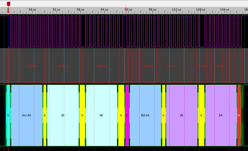
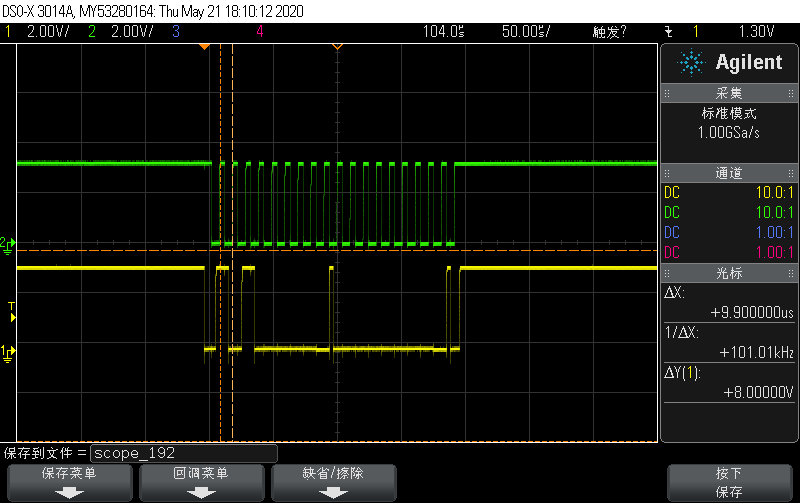
But when they read the data of address 0x00, they found the data is not correct, it is all 0xff. and the waveform are as below:
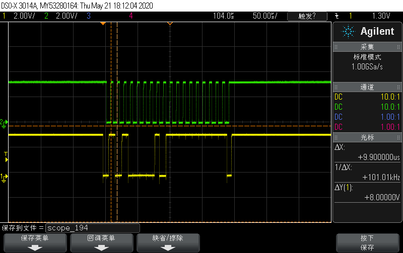
Any suggestion for this? below are the code that they are using:
//#############################################################################
//
// FILE:   i2c_ex1_slave_receive_int.c
//
// TITLE:  I2C Loopback with Slave Receive Interrupt
//
//! \addtogroup driver_example_cm_list
//! <h1>I2C Loopback with Slave Receive Interrupt</h1>
//!
//! This program shows how to configure a receive interrupt on the slave
//! module.  This includes setting up the I2C0 module for loopback mode as well
//! as configuring the master and slave modules.  Loopback mode internally
//! connects the master and slave data and clock lines together.  The address
//! of the slave module is set to a value so it can receive data from the
//! master.
//!
//! This is a 7-bit slave module address sent in the following format:
//!                      [A6:A5:A4:A3:A2:A1:A0:RS]
//!
//! A zero in the R/S position of the first byte means that the master
//! transmits (sends) data to the selected slave, and a one in this position
//! means that the master receives data from the slave.
//!
//! \b External \b Connections \n
//!  - None
//!
//! \b Watch \b Variables \n
//!  - \b ui32DataTx - Data to send
//!  - \b ui32DataRx - Received data
//!  - \b result - Status of the I2C communication
//!
//
//#############################################################################
// $TI Release: F2838x Support Library v3.01.00.00 $
// $Release Date: Thu Mar 19 07:48:04 IST 2020 $
// $Copyright:
// Copyright (C) 2020 Texas Instruments Incorporated - http://www.ti.com/
//
// Redistribution and use in source and binary forms, with or without
// modification, are permitted provided that the following conditions
// are met:
//
//   Redistributions of source code must retain the above copyright
//   notice, this list of conditions and the following disclaimer.
//
//   Redistributions in binary form must reproduce the above copyright
//   notice, this list of conditions and the following disclaimer in the
//   documentation and/or other materials provided with the
//   distribution.
//
//   Neither the name of Texas Instruments Incorporated nor the names of
//   its contributors may be used to endorse or promote products derived
//   from this software without specific prior written permission.
//
// THIS SOFTWARE IS PROVIDED BY THE COPYRIGHT HOLDERS AND CONTRIBUTORS
// "AS IS" AND ANY EXPRESS OR IMPLIED WARRANTIES, INCLUDING, BUT NOT
// LIMITED TO, THE IMPLIED WARRANTIES OF MERCHANTABILITY AND FITNESS FOR
// A PARTICULAR PURPOSE ARE DISCLAIMED. IN NO EVENT SHALL THE COPYRIGHT
// OWNER OR CONTRIBUTORS BE LIABLE FOR ANY DIRECT, INDIRECT, INCIDENTAL,
// SPECIAL, EXEMPLARY, OR CONSEQUENTIAL DAMAGES (INCLUDING, BUT NOT
// LIMITED TO, PROCUREMENT OF SUBSTITUTE GOODS OR SERVICES; LOSS OF USE,
// DATA, OR PROFITS; OR BUSINESS INTERRUPTION) HOWEVER CAUSED AND ON ANY
// THEORY OF LIABILITY, WHETHER IN CONTRACT, STRICT LIABILITY, OR TORT
// (INCLUDING NEGLIGENCE OR OTHERWISE) ARISING IN ANY WAY OUT OF THE USE
// OF THIS SOFTWARE, EVEN IF ADVISED OF THE POSSIBILITY OF SUCH DAMAGE.
// $
//#############################################################################
//
// Included Files
//
#include <stdint.h>
#include <stdbool.h>

#include "cm.h"

//
// Defines
//
#define SLAVE_ADDRESS   0x50
#define NUM_I2C_DATA    3
#define PASS 0
#define FAIL 1

//
// Globals
//
uint32_t result = FAIL;
uint32_t ui32DataTx;
static uint32_t ui32DataRx;

uint8_t rx_data = 0,Return_S = 0;
uint32_t PIN33_st = 0;
//
// Function Prototypes
//
void initI2C(void);
__interrupt void I2C0SlaveIntHandler(void);

//
// Main
//
void main(void)
{
    uint16_t i;

    //
    // disable WD, enable peripheral clocks.
    //
    CM_init();

    //
    // Enable the I2C0 interrupt on the processor (NVIC).
    //
//    I2C_registerInt(INT_I2C0,I2C0SlaveIntHandler);
    GPIO_writePin(33, 0);
    PIN33_st = GPIO_readPin(33);
    //
    // Set I2C use, initializing master and slave
    //
    initI2C();
    //
    // Synchronize both the cores.
    //
    IPC_sync(IPC_CM_L_CPU1_R, IPC_FLAG31);

    Return_S = I2C_Byte_Write(00,0xA5);

    Return_S = I2C_Byte_Read(00,&rx_data);

    //
    // Initialize the data to send.
    //
//    ui32DataTx = 'I';

    //
    // Place the data to be sent in the data register.
    //
//    I2C_putMasterData(I2C0_BASE, ui32DataTx);

    //
    // Initiate send of single piece of data from the master.  Since the
    // loopback mode is enabled, the Master and Slave units are connected
    // allowing us to receive the same data that we sent out.
    //
//    I2C_setMasterConfig(I2C0_BASE, I2C_MASTER_CMD_SINGLE_SEND);

    while(1)
    {
        //
        // Delay
        //
        for(i=1000; i>0; i--);
    }
}

//
// Function to configure I2C0.
//
void initI2C()
{

    I2C_disableMaster(I2C0_BASE);
    //step 4:Initialize the I2C master by writing the I2CMCS_WRITE register with a value of 0x0000.0010.
//    HWREG(I2C0_BASE + I2C_O_MCS_WRITE) = 0x00000010U;//TRM error???
    //
    // Enable the Master module.
    //
//    I2C_enableMaster(I2C0_BASE);

    //step 5:Set the desired SCL clock speed of 100 kbps by writing the I2CMTPR register with the correct value

    // I2C configuration. Set up to transfer data at 100 Kbps.
    //
    I2C_initMaster(I2C0_BASE,I2C_CLK_FREQ,false);

    //
    // Enable the Slave module.
    //
//    I2C_enableSlave(I2C0_BASE);

}

bool I2C_Byte_Write(uint16_t addr,uint8_t data)
{

    //
    // step 6: Specify the slave address of the master and that the next operation is a Transmit by writing the I2CMSA register with a value of 0x0000.0076. This sets the slave address to 0x3B.
    //
    I2C_setSlaveAddress(I2C0_BASE,SLAVE_ADDRESS,I2C_MASTER_WRITE);
    //step 7: Place data (byte) to be transmitted in the data register by writing the I2CMDR register with the desired data
    I2C_putMasterData(I2C0_BASE, addr>>8); //EEPROM address...

    // step 8: Initiate a single byte transmit of the data from master to slave by writing the I2CMCS register with a value of 0x0000.0007 (STOP, START, RUN)
    I2C_setMasterConfig(I2C0_BASE, I2C_MASTER_CMD_SINGLE_SEND);
    //step 9: Wait until the transmission completes by polling the BUSBSY bit in the I2CMCS register until it has been cleared
    while(I2C_isMasterBusy(I2C0_BASE));
    if(I2C_getMasterErr(I2C0_BASE) != 0)
    {
        //error
        return 1;
    }

    I2C_putMasterData(I2C0_BASE, addr); //EEPROM address...

     // step 8: Initiate a single byte transmit of the data from master to slave by writing the I2CMCS register with a value of 0x0000.0007 (STOP, START, RUN)
     I2C_setMasterConfig(I2C0_BASE, I2C_MASTER_CMD_SINGLE_SEND);
     //step 9: Wait until the transmission completes by polling the BUSBSY bit in the I2CMCS register until it has been cleared
     while(I2C_isMasterBusy(I2C0_BASE));
     if(I2C_getMasterErr(I2C0_BASE) != 0)
     {
         //error
         return 1;
     }
    // send data
    I2C_putMasterData(I2C0_BASE, data); //EEPROM address...

    // step 8: Initiate a single byte transmit of the data from master to slave by writing the I2CMCS register with a value of 0x0000.0007 (STOP, START, RUN)
    I2C_setMasterConfig(I2C0_BASE, I2C_MASTER_CMD_SINGLE_SEND);
    //step 9: Wait until the transmission completes by polling the BUSBSY bit in the I2CMCS register until it has been cleared
    while(I2C_isMasterBusy(I2C0_BASE));

    //step 10: Check the ERROR bit in the I2CMCS register to confirm the transmit was acknowledged.
    if(I2C_getMasterErr(I2C0_BASE) != 0)
    {
        //error
        return 1;
    }
}

bool I2C_Byte_Read(uint16_t addr,uint8_t* data)
{

    //
    // step 6: Specify the slave address of the master and that the next operation is a Transmit by writing the I2CMSA register with a value of 0x0000.0076. This sets the slave address to 0x3B.
    //
    I2C_setSlaveAddress(I2C0_BASE,SLAVE_ADDRESS,I2C_MASTER_WRITE);
    //high address
    //step 7: Place data (byte) to be transmitted in the data register by writing the I2CMDR register with the desired data
    I2C_putMasterData(I2C0_BASE, addr>>8); //EEPROM address...

    // step 8: Initiate a single byte transmit of the data from master to slave by writing the I2CMCS register with a value of 0x0000.0007 (STOP, START, RUN)
    I2C_setMasterConfig(I2C0_BASE, I2C_MASTER_CMD_SINGLE_SEND);
    //step 9: Wait until the transmission completes by polling the BUSBSY bit in the I2CMCS register until it has been cleared
    while(I2C_isMasterBusy(I2C0_BASE));

    if(I2C_getMasterErr(I2C0_BASE) != 0)
    {
        //error
        return 1;
    }
    //low address
    I2C_putMasterData(I2C0_BASE, addr); //EEPROM address...

    // step 8: Initiate a single byte transmit of the data from master to slave by writing the I2CMCS register with a value of 0x0000.0007 (STOP, START, RUN)
    I2C_setMasterConfig(I2C0_BASE, I2C_MASTER_CMD_SINGLE_SEND);
    //step 9: Wait until the transmission completes by polling the BUSBSY bit in the I2CMCS register until it has been cleared
    while(I2C_isMasterBusy(I2C0_BASE));

    if(I2C_getMasterErr(I2C0_BASE) != 0)
    {
        //error
        return 1;
    }

    I2C_setSlaveAddress(I2C0_BASE,SLAVE_ADDRESS,I2C_MASTER_READ);
    I2C_setMasterConfig(I2C0_BASE, I2C_MASTER_CMD_SINGLE_RECEIVE);
    // read data
    *data = I2C_getMasterData(I2C0_BASE); //EEPROM address...

}


//
// I2C0 Receive ISR.
//
 __interrupt void I2C0SlaveIntHandler(void)
{
    uint32_t slvStatus;

    //
    // Get the slave interrupt status
    //
    slvStatus = I2C_getSlaveIntStatus(I2C0_BASE,I2C_MASTER_RAW_INT);

    //
    // Clear the I2C0 interrupt flag.
    //
    I2C_clearSlaveInt(I2C0_BASE);

    //
    // Read the data from the slave.
    //
    ui32DataRx =  I2C_getSlaveData(I2C0_BASE);

    if(ui32DataRx != ui32DataTx)
        result = FAIL;
    else
        result = PASS;

    //
    // Clear the slave interrupt status
    //
    I2C_clearSlaveIntSource(I2C0_BASE,slvStatus);
}

//
// End of File
//