This thread has been locked.

If you have a related question, please click the "Ask a related question" button in the top right corner. The newly created question will be automatically linked to this question.

CCS/TMS320F28377D: Serial flash programmer problem - stop after kernel loading

Part Number: TMS320F28377D
Other Parts Discussed in Thread: C2000WARE, TMS320F28377S

Tool/software: Code Composer Studio

Dear experts.

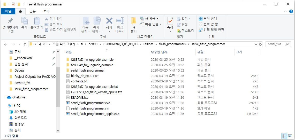
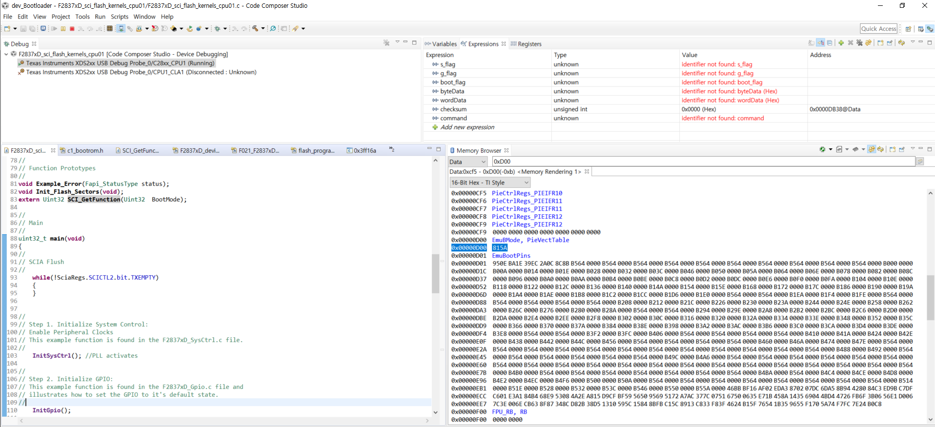
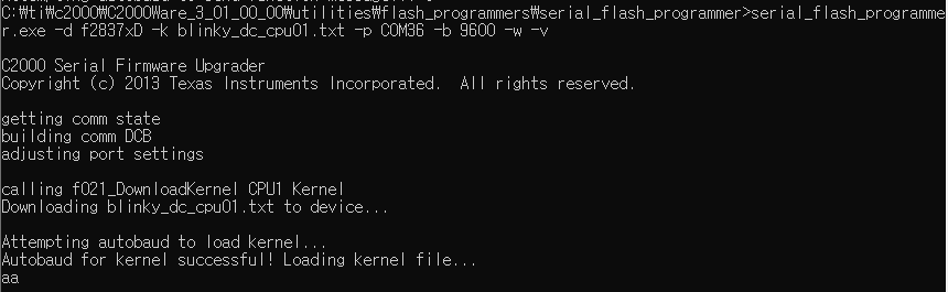
I was stuck to serial flash programmer example.

I used GPIO28,29 UART port.

and it used RS-232C transceiver.

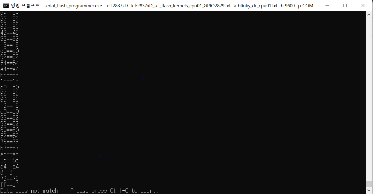
Why it made happens?

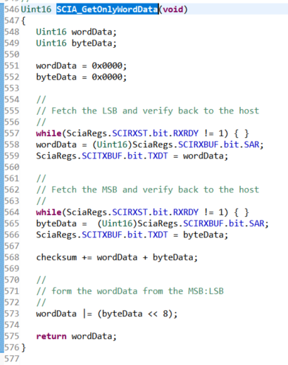
And I think, it was failed to autobaud function..

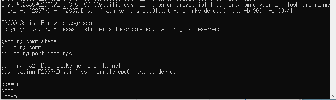
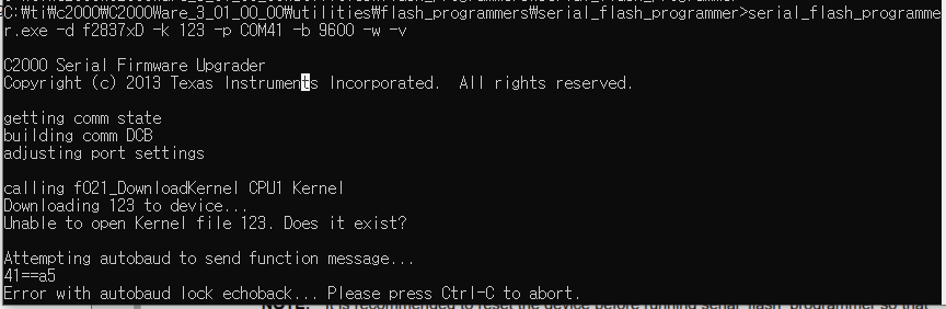
I retried command to the changed file name, it occurs refer to below things.

How fixed it?


Please give me advice.

Thanks

Best regards,

Edward

  • Edward,

    blinky_dc_cpu01.txt is an Application file, not a Kernel file.

    Your command needs to be something like:

    serial_flash_programmer.exe -d f2837xD -k F2837xD_sci_flash_kernels_cpu01.txt -a blinky_dc_cpu01.txt
    -b 9600 -p COM36

    As you might expect, with the above command, the kernel and application files need to be in the same location as the serial_flash_programmer.exe.

    Thanks,

    Sira

  • Dear Sira

    Thanks you for reply.

    I tried your advice, but I was occurred in the same situation.

    Please refer to below image.

    "aa" and "8" echo back was stranged.

    First of all the F2837xD_sci_flash_kernels_cpu01 example was not echo back to the "aa" message.

    So I uncommented SCIA_GetOnlyWordData() functions "SciaRegs.SCITXBUF.bit.TXDT = wordData;" codes. (refer to below image)
    Then the example could echo back "aa" and "8" messages.
    but as you saw the upper image, after "aa", "8" echo back, doesn't echo back.
    Please give me advice.

    And As you said, with the above command, the kernel and application files need to be in the same location as the serial_flash_programmer.exe.

    Please confirm it.

    Thanks.
    Best regards,
    Edward

  • Dear Sira

    I modified in example code.
    the code was SCI_BOOT_ALTERNATE of SCI_GetFunction() function in F2837xD_sci_flash_kernels_cpu01.c
    But the same problem occurred.

    And When I missed -w , -v command, some message instruction was gone.
    the missing message is below.
    "Attempting autobaud to load kernel..."
    "Autobaud for kernel successful! Loading kernel file..."


    And I have very important question.

    1. How run sci kernel flash programming example?

    My test report is below.

    1) I connected the debugger to the TMS320F28377D custom board.
    2) Uploaded firmware sci kernel flash programming example to a custom board.
    3) Custom board run
    That's it.

    So I think it must be set SCI boot mode in TMS320F28377D when the sci kernel example run.
    but I already upload the firmware using the debugger.
    So How set SCI boot mode?
    After uploading the firmware, the custom board executes reset command?
    Maybe sci kernel flash programming example is working only RAM. so I think it erases the code when executes reset command. right?

    2. To use GPIO28,29 in SCI Flash kernel programmer example, do I need to modify the OTP settings?
    Please tell me how you can use the example with GPIO28, 29.

    I'm looking forward to your advice.

    Thanks.
    Best regards,
    Edward

  • Edward,

    I have a few initial questions and comments:

    1. Are you using the latest version of C2000Ware? That is, where are you getting the F2837xD_sci_flash_kernels_cpu01 project from?

    2. Are you using Custom hardware or TI hardware? If TI hardware, which one?

    3. -v is verbose, which means more detailed messages will be printed to the console.

    4. SCI_BOOT_ALTERNATE is what you would need to use for GPIO 28, 29. Rebuild the SCI kernel project.

    //
    // parameter SCI_BOOT for GPIO84,85; parameter SCI_BOOT_ALTERNATE
    // for GPIO28,29
    //
    EntryAddr = SCI_GetFunction(SCI_BOOT);

    5. Yes, you need to use SCI Boot mode on the board, in order to be able to download the SCI Flash Kernel to RAM, which will then allow the Application to be downloaded to Flash. Then you will switch to Flash boot mode. When you reset the board, the SCI Flash Kernel will no longer be present, but the Application will run out of Flash.

    Thanks,

    Sira

  • Edward,

    I have a few initial questions and comments:

    1. Are you using the latest version of C2000Ware? That is, where are you getting the F2837xD_sci_flash_kernels_cpu01 project from?
    -> I'm using the latest version of C2000(C2000Ware_3_01_00_00)
    The .exe project locates are C:\ti\c2000\C2000Ware_3_01_00_00\utilities\flash_programmers\serial_flash_programmer.
    and the example locates are C:\ti\c2000\C2000Ware_3_01_00_00\device_support\f2837xd\examples\dual\F2837xD_sci_flash_kernels.


    2. Are you using Custom hardware or TI hardware? If TI hardware, which one?
    -> I'm using Custom hardware please refer to the below attached schematic.

    Schematic_F28377D-337_M_V100.pdf


    3. -v is verbose, which means more detailed messages will be printed to the console.
    -> OK

    4. SCI_BOOT_ALTERNATE is what you would need to use for GPIO 28, 29. Rebuild the SCI kernel project.
    -> I modified SCI_BOOT to SCI_BOOT_ALTERNATE. but also it same situation.
    //
    // parameter SCI_BOOT for GPIO84,85; parameter SCI_BOOT_ALTERNATE
    // for GPIO28,29
    //
    EntryAddr = SCI_GetFunction(SCI_BOOT);

    5. Yes, you need to use SCI Boot mode on the board, in order to be able to download the SCI Flash Kernel to RAM, which will then allow the Application to be downloaded to Flash. Then you will switch to Flash boot mode. When you reset the board, the SCI Flash Kernel will no longer be present, but the Application will run out of Flash.
    -> How testing sci kernel step by step? First of all, I would like to ignore Flash operation. I just want to test the pure sci flash example.

    If I tell the order I tested step by step, it looks like this:
    1.Set to TMS320F28377D SCI BOOT MODE using resistance (GPIO84 High, GPIO72 Low)
    2. Uploaded the firmware using the debugger.
    3. Removed debugger from the board after upload.
    4. Ran the command prompt.
    5. I moved to the path of serial_flash_programmer.exe and ran serial_flash_programmer.exe program.
    6. Serial_flash_programmer.exe -d f2837xD -k F2837xD_sci_flash_kernels_cpu01.txt -a blinky_dc_cpu01.txt -b 9600 -p COM41 command execution.
    7. The same symptoms occurred.

    Thanks,

    Best regards,

    Edward

  • Edward,

    It appears that if you want to use SCI Boot mode with GPIO 28, 29 on the F2837xD, you could do one of the following:

    Set BMODE field (bits 15:8) of the corresponding BOOTCTRL register (either EMUBOOTCTRL(0xD00) or Z1-BOOTCTRL (0x7801E which is in User configurable DCSM OTP) to 0x81). Also need to set the KEY (bits 7:0) of the corresponding BOOTCTRL register to 0x5A
    So this means if you don't want to write OTP yet, you could do Emulation mode, connect to CCS, write 0x815A to location 0xD00. Then Reset CPU in CCS and Run (i.e. leaving Emulator connected).
    Then in the command window, send the command like before:

    serial_flash_programmer.exe -d f2837xD -k F2837xD_sci_flash_kernels_cpu01-gpio2829.txt -a blinky_dc_cpu01.txt -b 9600 -p COM4 -v

    Remember that the kernel project must be built for GPIO 28,29 (hence I named it above).

    Once the kernel downloads to RAM, it will pop another command question, there select 1 for DFU CPU1, then it will Flash the application to Flash. Then disconnect CCS and switch to Flash boot mode and the reset the board and the blinky should run.

    Let me know what you find.

    Thanks,

    Sira

  • Dear Sira

    Thank you for reply.

    I failed the configured GPIO28,29 setting.
    So I found out other custom board, this custom board DSP was TMS320F28377S.
    So I connected GPIO84,85 default pins.
    And then tested it.
    Then we moved on to the next step.
    However, the following message is displayed.

    Is the F2837xD_sci_flash_kernels_cpu01.txt  file wrong ?? Or is there something else wrong ??

    Best regards,

    Edward

  • Edward,

    I have tested the F2837xD_sci_flash_kernel_cpu01.txt file on the F2837xD controlCARD using the method I described to you

    - by connecting the emulator and modifying the EMUBOOTCTRL register and running

    -  by building the .txt file using GPIO 28, 29.

    What does "I failed the GPIO 28, 29" setting mean?

    For 2837S, you cannot use the F2837xD file, you will have to use the F2837xS file.

    Thanks,

    Sira

  • Dear Sira.
    Thanks for reply

    I have tested the F2837xD_sci_flash_kernel_cpu01.txt file on the F2837xD custom board using the method as you said.
    I tested it like this:
    1. by connecting the emulator and executed debug mode and modifying the EMUBOOTCTRL register(0xD00) and running.
    2. by building the .txt file using GPIO 28, 29. (Please refer to below picture)

    3. I ran .exe files and then in the command window, sent the command like before:
    serial_flash_programmer.exe -d f2837xD -k F2837xD_sci_flash_kernels_cpu01-GPIO2829.txt -a blinky_dc_cpu01.txt -b 9600 -p COM36 -v

    4. The moment the command was sent, Firmware upload began.
    5. And It was working, But suddenly it was stopped while the data received. (Please refer to below picture) It always stopped from "ff == bf" part.

    I looking forward to your answer.

    Thanks,
    Best Regards,
    Edward.

  • Edward,

    Thanks for the updates. Do you have a F2837xD ControlCard and Docking station? That would allow you to test the files on it and validate the files, helping narrow down the issue.

    Thanks,

    Sira

  • Dear Sira

    Thanks for reply

    What is the F2837xD ControlCard and Docking station?
    How would allow to test the files on it and validate the files?

    Please tell me step by step specifically.

    I'm looking forward to your answer.

    Thanks

  • Hi Edward,

    It is TI hardware - like this http://www.ti.com/tool/TMDSDOCK28379D#buy

    It is what I have and how I validated the files.

    Thanks,

    Sira

  • Dear Sira.

    Thanks for reply.

    Actually I don't have time.

    Not enough time to do projects.

    And the controlCARD buy is taking the time.

    So please recommend the other solutions.

    I'm looking forward to your answers.

    Thanks

    Best regards,

    Edward

  • Edward,

    The following are suggestions:

    1. I think trying on the ControlCARD will help narrow down the issue - and help determine whether it is a Hardware issue (since you are using Custom hardware).

    2. A colleague suggested checking soldering on the board, as it was a solution for a recent issue they were dealing with that was similar.

    3. Perhaps try a lower baud rate and see if that helps.

    4. You could also run some tests using the SCI echoback example on your custom Hardware (C:\ti\c2000\C2000Ware_3_02_00_00\driverlib\f2837xd\examples\cpu1\sci)

    Thanks,

    Sira


  • Edward,

    Can I close this post for now? Once you try echoback example and control card, you can open a new post by using the "ask a related question" button at the top right corner of this webpage.  

    Thanks and regards,
    Vamsi