This thread has been locked.

If you have a related question, please click the "Ask a related question" button in the top right corner. The newly created question will be automatically linked to this question.

CCS/TMS320F28032: Can't connect in debug mode, but connection test succeeds

Part Number: TMS320F28032

Tool/software: Code Composer Studio

Hi,

I just soldered two boards and they have both the same failure. I can't debug, but the test connection sequence is done successfully:

So here is the log from the test sequence:

[Start]

Execute the command:

%ccs_base%/common/uscif/dbgjtag -f %boarddatafile% -rv -o -S integrity

[Result]


-----[Print the board config pathname(s)]------------------------------------

/Users/maxe/.ti/ccs930/1/0/BrdDat/testBoard.dat

-----[Print the reset-command software log-file]-----------------------------

This utility has selected a 100- or 510-class product.
This utility will load the adapter 'libjioxds110.dylib'.
The library build date was 'Nov 25 2019'.
The library build time was '15:02:58'.
The library package version is '8.4.0.00006'.
The library component version is '35.35.0.0'.
The controller does not use a programmable FPGA.
The controller has a version number of '5' (0x00000005).
The controller has an insertion length of '0' (0x00000000).
This utility will attempt to reset the controller.
This utility has successfully reset the controller.

-----[Print the reset-command hardware log-file]-----------------------------

The scan-path will be reset by toggling the JTAG TRST signal.
The controller is the XDS110 with USB interface.
The link from controller to target is direct (without cable).
The software is configured for XDS110 features.
The controller cannot monitor the value on the EMU[0] pin.
The controller cannot monitor the value on the EMU[1] pin.
The controller cannot control the timing on output pins.
The controller cannot control the timing on input pins.
The scan-path link-delay has been set to exactly '0' (0x0000).

-----[Perform the Integrity scan-test on the JTAG IR]------------------------

This test will use blocks of 64 32-bit words.
This test will be applied just once.

Do a test using 0xFFFFFFFF.
Scan tests: 1, skipped: 0, failed: 0
Do a test using 0x00000000.
Scan tests: 2, skipped: 0, failed: 0
Do a test using 0xFE03E0E2.
Scan tests: 3, skipped: 0, failed: 0
Do a test using 0x01FC1F1D.
Scan tests: 4, skipped: 0, failed: 0
Do a test using 0x5533CCAA.
Scan tests: 5, skipped: 0, failed: 0
Do a test using 0xAACC3355.
Scan tests: 6, skipped: 0, failed: 0
All of the values were scanned correctly.

The JTAG IR Integrity scan-test has succeeded.

-----[Perform the Integrity scan-test on the JTAG DR]------------------------

This test will use blocks of 64 32-bit words.
This test will be applied just once.

Do a test using 0xFFFFFFFF.
Scan tests: 1, skipped: 0, failed: 0
Do a test using 0x00000000.
Scan tests: 2, skipped: 0, failed: 0
Do a test using 0xFE03E0E2.
Scan tests: 3, skipped: 0, failed: 0
Do a test using 0x01FC1F1D.
Scan tests: 4, skipped: 0, failed: 0
Do a test using 0x5533CCAA.
Scan tests: 5, skipped: 0, failed: 0
Do a test using 0xAACC3355.
Scan tests: 6, skipped: 0, failed: 0
All of the values were scanned correctly.

The JTAG DR Integrity scan-test has succeeded.

[End]

And here the error, which I get on starting a debug session:

C28xx: Failed CPU Reset: (Error -1137 @ 0x6) Device is held in reset. Take the device out of reset, and retry the operation. (Emulation package 8.4.0.00006) 
C28xx: Trouble Reading Register PC: (Error -1137 @ 0x0) Device is held in reset. Take the device out of reset, and retry the operation. (Emulation package 8.4.0.00006) 
C28xx: Trouble Reading Register ST1: (Error -1137 @ 0x6) Device is held in reset. Take the device out of reset, and retry the operation. (Emulation package 8.4.0.00006) 
C28xx: GEL: Error while executing OnReset(-1): Target failed to read register ST1
	 at (ST1&~(0x0100)) [f28032.gel:292]
	 at C28x_Mode() [f28032.gel:32]
	 at OnReset(-(1))
C28xx: GEL: Error while executing OnTargetConnect(): Reset failed: retcode=-1
	 at GEL_Reset() [f28032.gel:93]
	 at OnTargetConnect()
C28xx: Flash Programmer: Warning: The configured device (TMS320F28032), does not match the detected device (). Flash Programming operations could be affected. Please consider modifying your target configuration file.
C28xx: Failed CPU Reset: (Error -1137 @ 0x0) Device is held in reset. Take the device out of reset, and retry the operation. (Emulation package 8.4.0.00006) 
C28xx: Trouble Reading Register PC: (Error -1137 @ 0x0) Device is held in reset. Take the device out of reset, and retry the operation. (Emulation package 8.4.0.00006) 
C28xx: Trouble Reading Register ST1: (Error -1137 @ 0x6) Device is held in reset. Take the device out of reset, and retry the operation. (Emulation package 8.4.0.00006) 
C28xx: GEL: Error while executing OnReset(-1): Target failed to read register ST1
	 at (ST1&~(0x0100)) [f28032.gel:292]
	 at C28x_Mode() [f28032.gel:32]
	 at OnReset(-(1))
C28xx: GEL: Error calling OnPreFileLoaded(): Reset failed: retcode=-1
C28xx: Trouble Writing Memory Block at 0x8000 on Page 0 of Length 0xe7: (Error -1137 @ 0x8002) Device is held in reset. Take the device out of reset, and retry the operation. (Emulation package 8.4.0.00006) 
C28xx: File Loader: Verification failed: Target failed to write 0x08000@Program
C28xx: GEL: File: /Users/maxe/git/Ridetronic/MotorController/workspace_RT_Uboot/test_pcb/Debug/test_pcb.out: Load failed.

So I see here a few things: Why can the test connection program toggle the reset pin and the debug session can not ? So do I have a HW problem or a SW problem? Can you read that out of the logs?

I purchased this controller: TMS320F28032PAGQ

 And here is my target xml file:

<?xml version="1.0" encoding="UTF-8" standalone="no"?>
<configurations XML_version="1.2" id="configurations_0">
    <configuration XML_version="1.2" id="configuration_0">
        <instance XML_version="1.2" desc="Texas Instruments XDS110 USB Debug Probe" href="connections/TIXDS110_Connection.xml" id="Texas Instruments XDS110 USB Debug Probe" xml="TIXDS110_Connection.xml" xmlpath="connections"/>
        <connection XML_version="1.2" id="Texas Instruments XDS110 USB Debug Probe">
            <instance XML_version="1.2" href="drivers/tixds510c28x.xml" id="drivers" xml="tixds510c28x.xml" xmlpath="drivers"/>
            <platform XML_version="1.2" id="platform_0">
                <instance XML_version="1.2" desc="TMS320F28032" href="devices/f28032.xml" id="TMS320F28032" xml="f28032.xml" xmlpath="devices"/>
            </platform>
        </connection>
    </configuration>
</configurations>

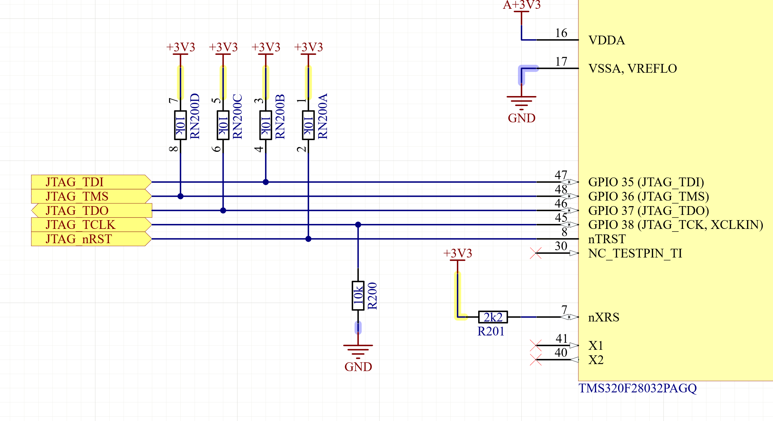
  • Here is my jtag pin 10 pinout:

    And here the XRS pin:

  • ok, so I found out, that I had the reset pin permanently driven high. That is solved.

    Now, the test still succeeds, but when I try to launch a debug session, I get this error:

    Error connecting to the target:

    (Error -1135 @ 0x0)

    The debug probe reported an error. Confirm debug probe configuration and connections, reset the debug probe, and retry the operation.

    (Emulation package 8.4.0.00006)

  • So, I found in another forum questions, there might be an issue with the nRST line. So looked with oscilloscope. It stays low all the time. I tried with no pull-down, with 2.2k Ohm pull-down, with 10k pull-down (as suggested in other resolved issues regarding this topic) - the XDS110 never pulls the Reset line high. I measured once again resistance between reset-line and GND - it is 10k.

    So XDS110 should be able to pull it high, right?

    And it is pin 10 on the 10-pin connector, right ?

    Why is the test connection tool claiming, that it resetted the device successfully, when this is absolutely not the case ? 

    Might be something broken in my XDS110 ? It is brand-new, I just received it.

  • Ferdinand,

    While pin 10 is nReset for ARM specific JTAG connection, I don't beleive this is equivalent to TRSTn as implemented on TI specific MCU/Processors.

    Looking at the adapter pinout in the XDS110 UG http://www.ti.com/lit/sprui94 on page 25 the adapter does not bring TRSTn signal to the Reset header on the 10 pin adapter(it is not brought out at all), this would also align to what you are seeing wrt TRSTn staying low(there is a small internal PD on this signal inside the MCU).

    If you have the 10 pin JTAG header on your physical board, we may need to build a small transposer to take the 14-pin connector to the correct pins.

    Let me know if I'm mis-reading the above, and we can further debug.

    Best,

    Matthew

  • Hi Mathew,

    thanks for your reply. Do I get you right: I can not program my CPU with the standard jtag-10 pinout? I need the old 14-pin? Can you share how the transposer (pinout) should look like between 14 and 10-pin? 

    I looked on the DRV8353-Eval board and the programming (what I see, is just normal hooked up). Isn't it 

    MD017A_Sch.pdf

  • Hi,

    so I found out, that on the 20-pin to 10-pin adapter you can change one Zero Ohm Jumper, and now the TRST pin is routed through pin 10.

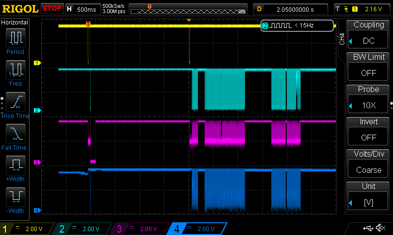
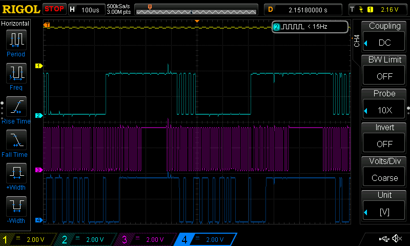
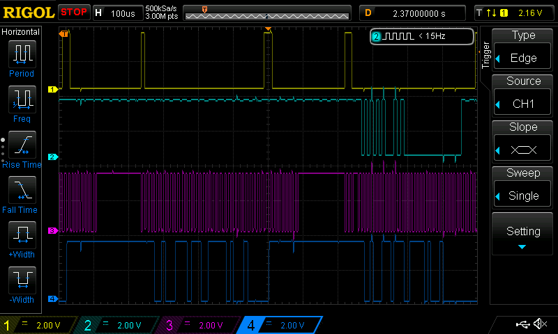
    Now I see the reset line toggling. But, unfortunately it is still not working... I see, definitely a reset toggle on the reset line, but why is CCS complaining, that device is holded in reset ? And still the question: Why is the Test Connection working successfully, but debugging/loading program is not possible?

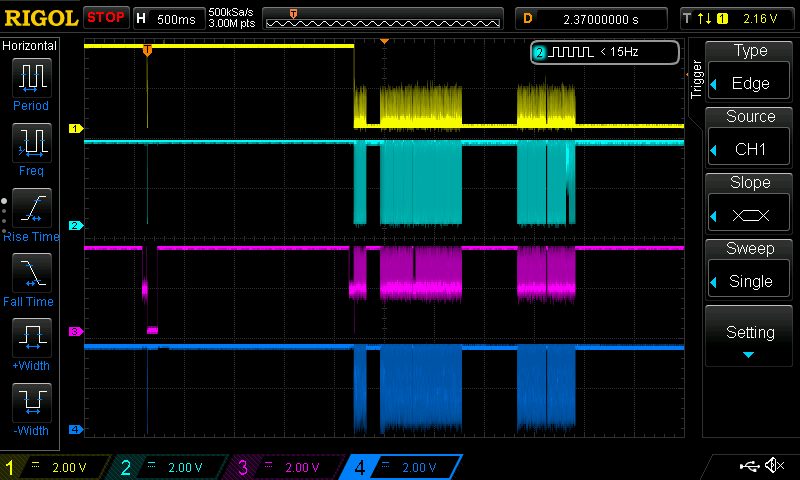
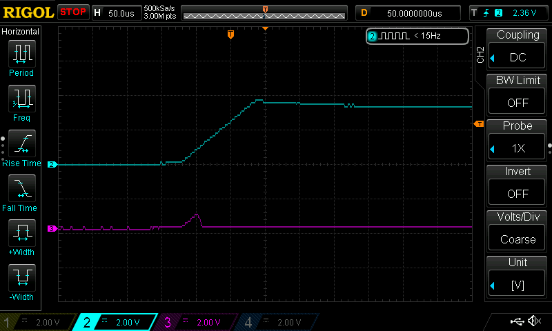
    I attached you screenshots from oscilloscope from all JTAG lines. For me nothing suspicious is seen here. (The first two pictures, yellow line is TRST line), on the last 2 pictures: yellow is TMS line:

    And now changed yellow line to TMS line:

  • I'm really a bit desperate after this day...

    I really do not get why the XDS110 thinks that the device is in reset ? 

    As you can see in the first image, which I posted yesterday: Reset line is going from high to low. Twice. 

    Also, another thing: 

    C28xx: Flash Programmer: Warning: The configured device (TMS320F28032), does not match the detected device (). Flash Programming operations could be affected. Please consider modifying your target configuration file.

    I bought this one TMS320F28032PAGQ and I selected "TMS320F28032" - this should be correct. Or do miss something else?

    Signals are all there: yellow reset line, light blue: TDI; dark blue: TDO; purple: TCK.

    I mean in the datasheett is written: 

    On the 2803x device, the JTAG port is reduced to 5 pins (TRST, TCK, TDI, TMS, TDO). TCK, TDI, TMS). So it should work with these 5 pins, right ?

    I see signals ongoing on each line.

    My error is still:

    C28xx: Failed CPU Reset: (Error -1137 @ 0x6) Device is held in reset. Take the device out of reset, and retry the operation. (Emulation package 8.4.0.00006) 
    
    C28xx: Trouble Reading Register PC: (Error -1137 @ 0x0) Device is held in reset. Take the device out of reset, and retry the operation. (Emulation package 8.4.0.00006) 
    
    C28xx: Trouble Reading Register ST1: (Error -1137 @ 0x6) Device is held in reset. Take the device out of reset, and retry the operation. (Emulation package 8.4.0.00006) 
    
    C28xx: GEL: Error while executing OnReset(-1): Target failed to read register ST1
    
    at (ST1&~(0x0100)) [f28032.gel:292]
    
    at C28x_Mode() [f28032.gel:32]
    
    at OnReset(-(1))
    
    C28xx: GEL: Error while executing OnTargetConnect(): Reset failed: retcode=-1
    
    at GEL_Reset() [f28032.gel:93]
    
    at OnTargetConnect()
    
    C28xx: Flash Programmer: Warning: The configured device (TMS320F28032), does not match the detected device (). Flash Programming operations could be affected. Please consider modifying your target configuration file.
    
    C28xx: Failed CPU Reset: (Error -1137 @ 0x0) Device is held in reset. Take the device out of reset, and retry the operation. (Emulation package 8.4.0.00006) 
    
    C28xx: Trouble Reading Register PC: (Error -1137 @ 0x0) Device is held in reset. Take the device out of reset, and retry the operation. (Emulation package 8.4.0.00006) 
    
    C28xx: Trouble Reading Register ST1: (Error -1137 @ 0x6) Device is held in reset. Take the device out of reset, and retry the operation. (Emulation package 8.4.0.00006) 
    
    C28xx: GEL: Error while executing OnReset(-1): Target failed to read register ST1
    
    at (ST1&~(0x0100)) [f28032.gel:292]
    
    at C28x_Mode() [f28032.gel:32]
    
    at OnReset(-(1))
    
    C28xx: GEL: Error calling OnPreFileLoaded(): Reset failed: retcode=-1
    
    C28xx: Trouble Writing Memory Block at 0x8000 on Page 0 of Length 0xe7: (Error -1137 @ 0x8002) Device is held in reset. Take the device out of reset, and retry the operation. (Emulation package 8.4.0.00006) 
    
    C28xx: File Loader: Verification failed: Target failed to write 0x08000@Program

  • Ok, now I looked at the XRS pin, it is low, but I have 2.2k Resistor pull-up on this pin. As far I understood this pin should be high... Will investigate now this issue...

  • Hi,

    so, I did some further investigations. Here is a screenshot from my 3.3 volt supply (blue) and the XRS Pin (purple) on start-up with a pull-up 2.2 kOhms between XRS and 3.3V:

    Do you think any problem in power supply? 

    So, afterwards I tried holding XRS directly at 3.3 V, but this leads to this error, when I try to load a program into the device:

    C28xx: GEL Output: 
    Device Calibration not complete, check if device is unlocked and recalibrate.C28xx: GEL Output: 
    Device Calibration not complete, check if device is unlocked and recalibrate.C28xx: File Loader: Verification failed: Values at address 0x08000@Program do not match Please verify target memory and memory map.

  • Ferdinand,

    Can you also check the 1.8V supply?  XRSn will not be released until both 3.3V and 1.8V supplies reach a minimum threshold.

    -Tommy

  • Hi Tommy,

    that was the right tip. We connected VDDIO with VDD, so VDD pins were also supplied with 3.3V. I did not see, that the VDD pins should not be connected to the VDDIO 3.3V since it is running with 1.8V.

    Processor survived and I can program it now. 

    Problem solved.