For some specific research, i have the task to implement open loop v/f control of ACI motor with 6-step pwm. I used dmclib as base for my v/f module and counter module providing frequency control. As for PWM generation, i intended to use the bldcpwm code, however this module uses commutation scheme, where at any time only two gates used, with high gates being controlled by PWM, and low switches being fully opened. Classic 6-step scheme, which i need, implies 3-switch operation
As rough example, inverter scheme:
1 3 5
4 6 2
where 1 is phase A high gate, 4 phase A low gate and so on.
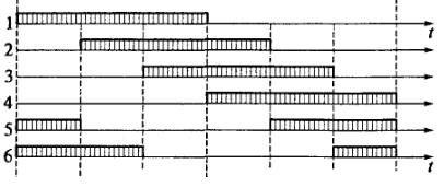
First state: gates 1, 5 and 6 are opened
Second state: 1, 6 and 2 are opened. Next image explains it better:

Its not really clear to me, what to do if i want to control output voltage level. For now i came up with next decision: inside every step, control same side gates with pwm and leave other side gate opened. Code example for first state:
if (p->State==0) // 1,5,6
{
EPwm1Regs.AQCSFRC.bit.CSFA = 0;
EPwm1Regs.AQCTLA.bit.CAU = 2;
EPwm1Regs.AQCTLA.bit.ZRO = 1;
EPwm1Regs.CMPA.half.CMPA = (int)(CMPVal); // 1A - pwm
EPwm1Regs.AQCSFRC.bit.CSFB = 1; // 1B - off
EPwm2Regs.AQCSFRC.bit.CSFA = 1; // 2A - off
EPwm2Regs.AQCSFRC.bit.CSFB = 2; // 2B - on
EPwm3Regs.AQCSFRC.bit.CSFA = 0;
EPwm3Regs.AQCTLA.bit.CAU = 2;
EPwm3Regs.AQCTLA.bit.ZRO = 1;
EPwm3Regs.CMPA.half.CMPA = (int)(CMPVal); // 3A - pwm
EPwm3Regs.AQCSFRC.bit.CSFB = 1; // 3B - off
}
I didnt do real tests with machine yet, so it is unknown if i am right, or totally wrong, so i would appreciate any opinions and advices.

