This thread has been locked.

If you have a related question, please click the "Ask a related question" button in the top right corner. The newly created question will be automatically linked to this question.

TMS320F28388D: PLL accuracy

Part Number: TMS320F28388D
Other Parts Discussed in Thread: TMDXCNCD28388D, C2000WARE

Hello,

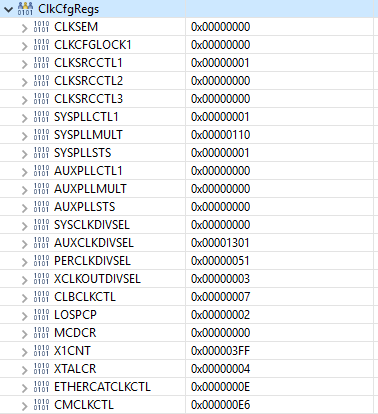
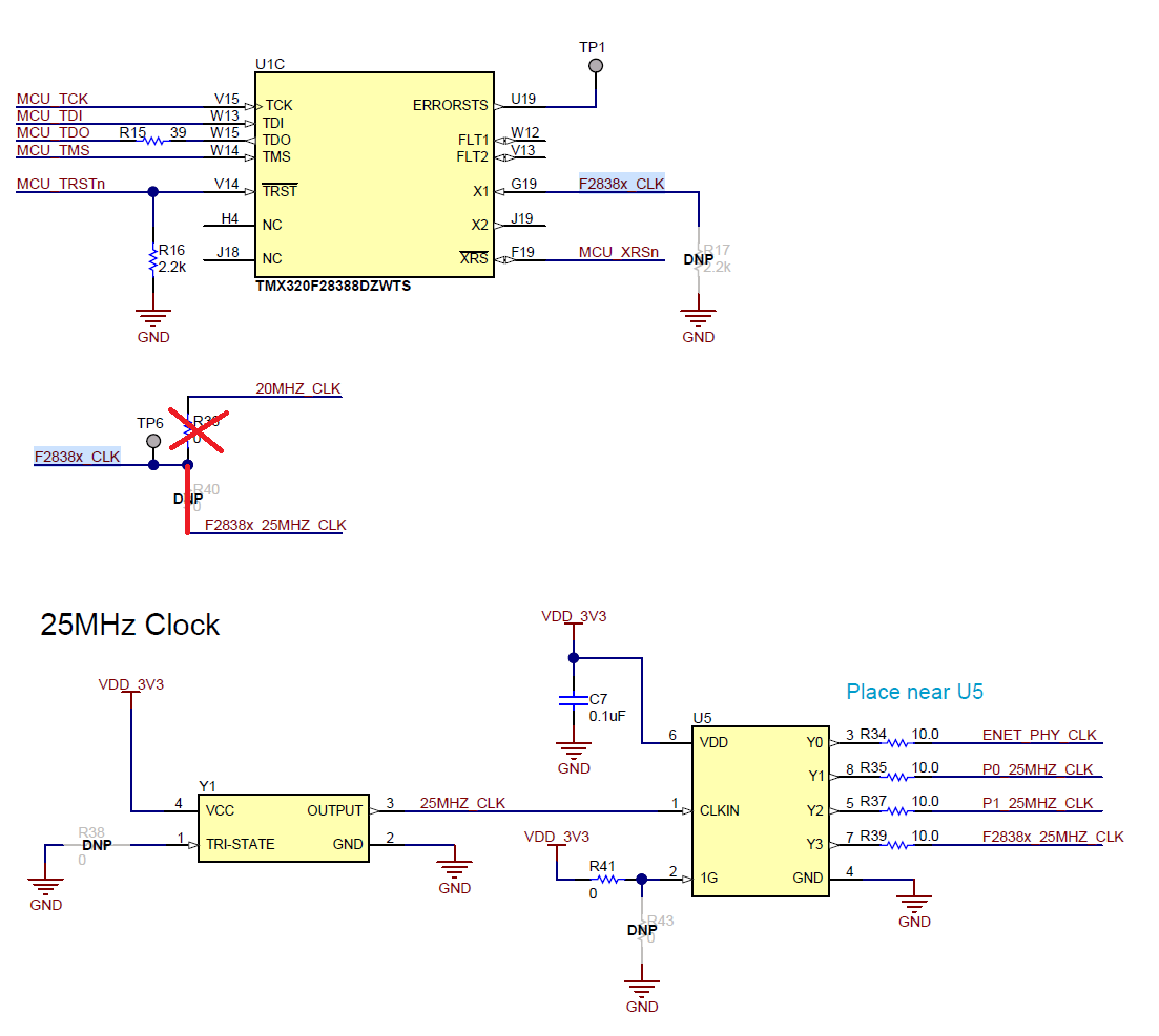
I am using TI Eval board (TMDXCNCD28388D) with F28388D processor. The input clock is configured as 25MHz (0-ohm resistor selector changed from default 20MHz (R36 removed, R40 added). Requested SysCLK frequency is 200MHz. I found that using different PLL settings (REFDIV,ODIV,IMULT) I get clock frequency close to requested 200MHz but frequency error strongly depends on PLL setting. Error vary from 0.6% to 3.4%.

For verification I have used two independent methods:
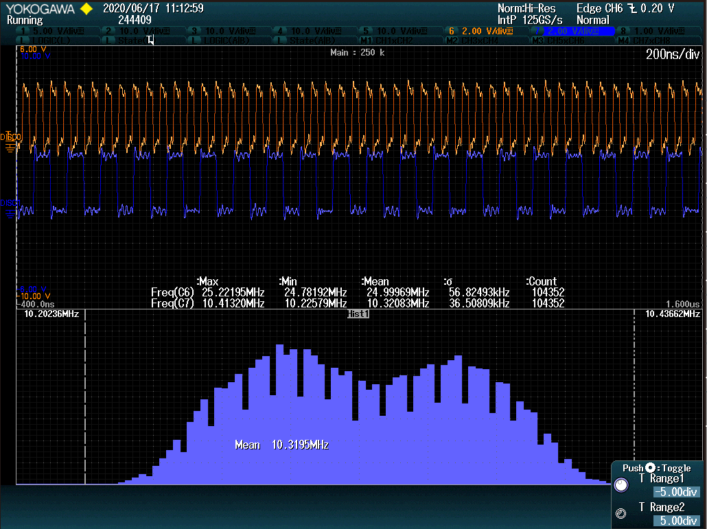
1. Toggle GPIO (1 toggle per n-th PWM periods) to measure frequency using osciloscope.
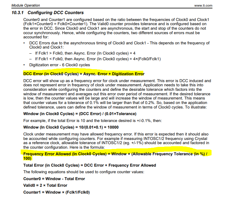
2. Using DCC - code is from C2000Ware examples (compare input to output clock frequency ratio.)
Each time I get correlated results from both methods - in this way I claim error not come from verification error and does not depends on input clock.

Moreover, the best results I get so far was with severe specification violation (INTCLK=5MHz or lower).

Example settings I have applied:
1.
REFDIV=0x04;
IMULT=0x50;
ODIV = 0x00;
SYSCLK_DIV = 0x01;

which results in error ~0.8%

2.
REFDIV=0x01;
IMULT=0x10;
ODIV = 0x00;
SYSCLK_DIV = 0x00;

which results in error ~1.5%


Questions:
1. Where this error come from?
2. Why frequency error depends on PLL settings?
3. Are there any known issues with clock/PLL circuitry on Evaluation Board?

Best Regards,

Milosz Przybylowicz

  • Hi Milosz,

    If you look at #2 settings it is putting VCOCLK frequency to 200MHz, it is violating minimum frequency spec for VCOCLK of 220MHz.

    Which DCC code are you referencing for validating PLL frequency? Can you please share that?

    To answer your questions:

    1. I am suspecting error is related to out of spec VCOCLK frequency.

    2. Frequency error should not vary drastically across PLL settings, it may vary by +/-0.1-+/-0.3% not more. 

    3. I dont anticipate any issues with the clock/pll circuit on the board, you could verify XTAL frequency by bringing it out on XCLKOUT to make sure it is at 25MHz.

    Regards,

    Nirav

  • Hi Nirav,

    thank you for quick response.

    Please note that I did not list all settings I have tried. So I double check with following settings:

    REFDIV=0x00;
    IMULT=0x10;
    ODIV = 0x01;
    SYSCLK_DIV = 0x00;

    Now, up to my knowledge, the specification is not violated (INTCLK = 25MHz, VCOCLK = 400MHz, PLLRAW = 200MHz) but frequency error can be easily detected (for example with DCC)

    Below is the code I use to verify clock - it is slightly modified version from C2000Ware library; I am using 'PLL_CLK_TOLERANCE' as a parameter - 1% cause IsPLLValid return FALSE, 2% will work. 

    BOOLEAN IsPLLValid(void)
    {
       BOOLEAN pllValid = FALSE;
       float fclk1_0ratio = 0.0;
       UINT32 window = 0;
       UINT32 dccCounterSeed0 = 0;
       UINT32 dccValidSeed0 = 0;
       UINT32 dccCounterSeed1 = 0;
       UINT32 total_error = 0;
    
    
       fclk1_0ratio = (float)PLL_IMULT / ((PLL_ODIV + 1U) * (PLL_REFDIV + 1U));
    
       if(fclk1_0ratio >= 1U)
       {
          total_error = 10U;
          window = (10U * 100U) / PLL_CLK_TOLERANCE;
       }
       else
       {
          total_error = (((UINT32)4 / fclk1_0ratio) + (UINT32)6);
          window = ((total_error * 100U)/ PLL_CLK_TOLERANCE);
       }
    
       dccCounterSeed0 = window - total_error;
       dccCounterSeed1 = window * fclk1_0ratio;
       dccValidSeed0 = (Uint32)2U * total_error;
    
       CpuSysRegs.PCLKCR21.bit.DCC0 = 1; /* Enable peripheral clock */
    
       Dcc0Regs.DCCSTATUS.bit.ERR = 1; /* Clear 'Error' bit */
       Dcc0Regs.DCCSTATUS.bit.DONE = 1; /* Clear 'Done' bit */
       Dcc0Regs.DCCGCTRL.bit.DCCENA = 0x5; /* Stop counters */
       Dcc0Regs.DCCGCTRL.bit.ERRENA = 0x5; /* Disable 'Error' signal */
       Dcc0Regs.DCCGCTRL.bit.DONEENA = 0x5; /* Disable 'Done' signal */
       Dcc0Regs.DCCCLKSRC1.all = 0xA000; /* Clk Src1 = PLLRAWCLK */
       Dcc0Regs.DCCCLKSRC0.all = 0xA000; /* Clk Src0 = XTAL */
       Dcc0Regs.DCCCNTSEED0.bit.COUNTSEED0 = dccCounterSeed0;
       Dcc0Regs.DCCVALIDSEED0.bit.VALIDSEED = dccValidSeed0;
       Dcc0Regs.DCCCNTSEED1.bit.COUNTSEED1 = dccCounterSeed1;
       Dcc0Regs.DCCGCTRL.bit.SINGLESHOT = 0xA; /* Single Shot Mode */
       Dcc0Regs.DCCGCTRL.bit.DCCENA = 0xA; /* Enable DCC */
    
       /* Wait until Error or Done Flag is generated */
       while((Dcc0Regs.DCCSTATUS.bit.DONE == 0) &&
             (Dcc0Regs.DCCSTATUS.bit.ERR == 0))
       {
          /* TODO: timeout */
       }
    
       if(Dcc0Regs.DCCSTATUS.bit.DONE == 1)
       {
          pllValid = TRUE;
       }
       else
       {
          pllValid = FALSE;
       }
    
       return pllValid;
    }
    

    and the function is called during PLL setup, just before applying SYSYCLKDIV (PLL is bypassed all the time):

       pllValid = IsPLLValid();
    
       if(TRUE == pllValid)
       {
          ClkCfgRegs.SYSCLKDIVSEL.bit.PLLSYSCLKDIV = SYSCLK_DIV;
       }
       else
       {
          /* error handling */
          asm(" ESTOP0");
       }
    

    Regards,

    Milosz

  • Hi Milosz,

    These PLL settings looks fine. Also, the DCC code looks correct. I have couple of questions:

    1. Are you saying by setting PLL_CLK_TOLERANCE=1%, IsPLLValid() function returns "FALSE", but with 2% it returns "TRUE"?

    2. Can you provide DCC register dump (All DCC registers) after executing IsPLLValid function?

    Thanks,

    Nirav

  • Nirav,

    Ad.1. Yes, that is right.

    Ad. 2. 

    case 1: IsPLLValid returns TRUE

    #define PLL_CLK_TOLERANCE (FLOAT32)1.8 /* [%] */


    case 2: IsPLLValid returns FALSE

    #define PLL_CLK_TOLERANCE    (FLOAT32)1.4 /* [%] */

    Regards,

    Milosz

  • Hi Milosz,

    For the register dump that you provided in both the cases, what is the PLL configuration used? Is it not below:

    REFDIV=0x00;
    IMULT=0x10;
    ODIV = 0x01;
    SYSCLK_DIV = 0x00;

    Can you also check with the total error=12, in your code to see what happens?

    Regards,

    Nirav

  • Nirav,

    almost, correct. The register dump I provided was with following settings:

    IMULT = 0x10
    REFDIV = 0x00
    ODIV = 0x00
    SYSCLK_DIV = 0x01

    but with ODIV=1, SYSCLK=0 I get exactly the same results.

    Regarding total error = 12

    Check pass with 1.4%, fail with e.g. 1.0%.

    Regards,

    Milosz

  • Hi Milosz,

    Thanks. Can you send me similar DCC register dump with Total Error = 12, and fail with 1% tolerance?

    How about if you make the  Total Error = 14 or 16? 

    Thanks & Regards,

    Nirav

  • Nirav,

    I took couple more measurement and here are results:

    Total error = 12, Tolerance = 1%, result = FALSE

    Total error = 14, Tolerance = 1%, result = FALSE

    Total error = 16, Tolerance = 1%, result = FALSE

    Total error = 18, Tolerance = 1%, result = TRUE

    Regards,

    Milosz

  • Hi Milosz,

    Thanks for your quick response, can you also dump clk_cfg_regs (mainly clksrcctl1 and PLLSYSCLKDIV) for any of the above failing configurations?

    Regards,

    Nirav

  • Nirav,

    all ClkCfgRegs (at the moment of leaving IsPLLValid function) are listed below. Please note that PLLSYSCLKDIV settings is applied after PLL clk is validated.

    Regards,

    Milosz

  • Hi Milosz,

    Thanks, their are 2 possibilities based on the data you provided:

    1. XTAL frequency is drifting over time, and hence when you set the tolerance to high value like 2.5% you see a pass, but with a lower tolerance value like 1% you see it a fail.

    2. Async error in DCC is higher than 10 (probably 18) and hence you are seeing a fail. This seems unlikely, because based on your first message, you are seeing similar % error when you are capturing ePWM output, but still cannot rule it out.

    Can you please run couple of more experiments? Hopefully it will help isolate the problem.

    1. Can you scope out XTAL frequency on o-scope using XCLKOUT and plot the frequency variation over time?

    2. Using Total Error=12 and tolerance of 1%, override dccCounterSeed1=0xFFFFF (instead of using formula  dccCounterSeed1 = window * fclk1_0ratio). Set this to higher value so that counter1 does not expire, and please provide dump of DCC registers.

    Regards,

    Nirav

  • Nirav,

    If I understood correctly, DCC measurement is immune to clock source frequency drift - it measure only ratio between two clock signals.

    Ad.1

    I measured input clock signal and PLLCLK/8 (CLKSRC3 = 0, XCLKOUTDIV = 3)  over period of several hours, so statistical information is rather good. Please find results below:

    Orange (C6) - input clock (measured on TP6)

    Blue (C7) - PLLCLK/8

    I did measure also XTAL on XCLKOUT (CLKSRC3=7, div=0) and results are nearly identical to those presented on first chart.

    Ad.2.

    Please find attached DCC regs dump:

    Additional information:

    The PLL frequency error seems to change also based on binary application which is loaded to microcontroller. Yesterday I did integrate other part of code to main project (completely irrelevant to PLL settings) and error is now slightly higher. I do remember that some time ago I had to increase tolerance in order to make new application running (on the same board). Of course no changes on PLL settings were made that time.

    I will be out of the office till 15th of June.

    Regards,

    Milosz

  • Hi Milosz,

    Thanks for the data, this is really useful in debugging the issue.

    Few questions on the plots:

    1. What is the sample size and time span of both the histograms (XTAL freq. and PLL freq)?

    2. PLL frequency histogram (in blue) markers shows different values of frequency than the one's shown in the bottom stats (that has min, max, stdev etc.)?

    3. What is the time scale of histogram (time per divison)?

    4. Are you using XTAL in a single ended mode ore connecting to X1 and X2?

    Few observations from your data (based on my interpretation of the scale)

    1. XTAL frequency histogram (orange) seems to span from -400ns to 1.6us, which is 2us. And in this period of 2 us XTAL frequency drifts from 24.78MHz-25.2MHz, which is about ~420KHz (1.7% total error).

    2. PLL frequency histogram (blue) has spikes at regular intervals, which suggests that input XTAL frequency drift happens in a step. And as you might know PLL is feedback loop which locks the i/p phase to the o/p phase of the PLL, hence it is trying to re-lock to changing input XTAL frequency.

    3. If you look at the DCC counter ratio which is Counter1/(Counter0+valid0) = (0xFFFFF-0xFBEA9)/(0x3DC+0x18) = 16.5, which is off by 0.5 (as the configured ratio is 16). This suggests 2 things, either DCC synchronization error is really high almost 2% that is making the ratio 16.5 or PLL is drifting to different frequency and overclocking DCC counters (which is likely the scenario now that we looked at the frequency plots which shows spikes).

    4. Window of DCC Counter measurements is Counter0+Valid0=1012 Clock0 counts = 40.48us (considering 25MHz/40ns input period), can you plot frequency histogram of both XTAL and PLL frequency for time span of 50us? Also, from your earlier data when you were setting Tolerance value to high number you were seeing a pass, but when you moved it to lower value you got a failure. This observation is supported by the plots you sent, where when the window of DCC measurement is small (With higher tolerance) it shows a pass.

    Overall I feel the XTAL frequency is not clean and has high ppm value, hence PLL is drifting and causing a failure. You can account for XTAL frequency accuracy/error of 2% in the DCC calculation as shown below. Image below is from the latest TRM release, C2000Ware will be updated in the next release.

    One more thing just to isolate the problem, can you run PLL with INTOSC2 as a clock source? And collect frequency plot of INTOSC2 using XCLKOUT and PLL frequency. You can also dump the DCC registers similarly using clock sourc0 as INTOSC2.

     Thanks,

    Nirav

  • Nirav,

    Histograms generated by this oscilloscope are only to visualize distribution and they do not provide any detailed information. 

    Ad.1:

    I do not have exact numbers. Oscilloscope has collected ~27000 samples over several hours.

    Ad.2:

    Blue is Channel 7 (C7), Orange is C6. I did not notice that in both pictures there is stat data for Channel 6 and looks like all screenshots I took has the same issue. The only information from PLL histogram that remains in pictures is the histogram boundary: f_min=25.7, f_max=26,2 and f_mean ~= 25.7MHz. The most important is that center frequency of PLL is higher by ~0.7MHz on PLL (blue) and it is much wider (see histogram min/max cursors on both C6 and C7)

    Ad.3:

    XTAL (C6) frequency span: ~0.5MHz

    PLL (C7) frequency span: ~1.8MHz

    Ad.4:

    Single ended. Eval board only modification was different clock source (see picture):

    My comments to your comments :)

    -400ns to 1600ns is TIME DOMAIN span - it has no application to frequency histograms. It is asymmetric because trigger point is set to 20% of screen (see T marker on top).

    1 sample on histogram represent 1 frequency measurement (which is taken over 2us time window). In total there are ~27k samples on histogram.

    I do not have a possibility to measure clock stability over short period of time (50us) that I would trust.

    I can provide another measurement results with INTOSC as clock source tomorrow.

    Regards,

    Milosz

  • Nirav,

    please find another measurement (samples collected overnight):

    Blue (C7) is PLL/8 with CLKSRCCTL1.OSCCLKSRCSEL= INTOSC2 

    Orange (C6) is external clock source (25MHz) - for reference only.

    Regards,

    Milosz

  • Hi Milosz,

    Thanks for providing data!!

    What is the PLL configuration with clock source as INTOSC2? Can you use the multipliers which can get the PLLCLKOUT same as you get with XTAL=25Mhz?

    Thanks can you also dump the DCC registers with INTOSC2 as the clock source, Using Total Error=12 and tolerance of 1%, override dccCounterSeed1=0xFFFFF (instead of using formula  dccCounterSeed1 = window * fclk1_0ratio). Set this to higher value so that counter1 does not expire, and please provide dump of DCC registers.

    Regards,

    Nirav

  • Nirav,

    Previous PLL configuration was identical to one with external clock source.

    Please find requested data below:

    PLL_IMULT 0x28
    PLL_REFDIV 0
    PLL_ODIV 0
    SYSCLK_DIV 1
    PLL_CLK_TOLERANCE 1 /* [%] */

    Regards,

    Milosz

  • Hi Milosz,

    Thanks for the data, its not completely clear though if the error is source induced or coming from PLL, since the drift in XTAL/INTOSC frequency is > 1%.

    We do expect about 0.5% error coming from PLL, so I suggest to account for that in your calculation, and make the Total Error = 17, keeping the window same as 1000.

    Hopefully that will solve the problem.

    Regards,

    Nirav

  • Nirav,

    XTAL/INTOSC drift does not explain why average PLL frequency is always higher than expected.

    Where is this 0.5% error comes from?  Is it constant 0.5% error, in whole specification range? Can you point a document which describes PLL error?

    'Total Error' is for me a parameter to clock verification routine. I can easily bypass this routine or adjust other parameters (e.g. tolerance = 5%) but it does not affect PLL output clock which is the main problem here.

    Regard,

    Milosz

  • Hi Milosz,

    I am not completely sure why PLL frequency is always higher, but it could be that XTAL drifts beyond certain range and is causing PLL to loose lock, and while re-locking it overshoots, and maybe that is the reason that it always shows higher frequency. 

    Typically we expect error in PLL frequency to be < 0.1%, but we have seen corner cases that may go up to 0.5% (its seems unlikely, but definitely possible).

    No, currently we dont have spec on PLL output frequency error, but will take a note to add in the next release.

    Is 0.5% error in SYSCLK too high for your system requirements?

    I have couple of suggestions that may help narrow down the issue:

    1. Can you use below configuration and check the PLL frequency, here we are trying to lower the VCO frequency and see if it helps?

    XTAL=25MHz, REFDIV=1, IMULT=9, ODIV=1, SYSCLKDIV=1. By doing this we are keeping VCO=225MHz. 

    2. Use AUXPLL (2nd PLL on the device) with same failing configuration, and check if you are seeing same 0.5% error on AUXPLL output frequency, if it is then most likely the source of the problem is XTAL drift. But if not, then it could be that SYSPLL has higher error.

    Regards,

    Nirav