


Dear team:
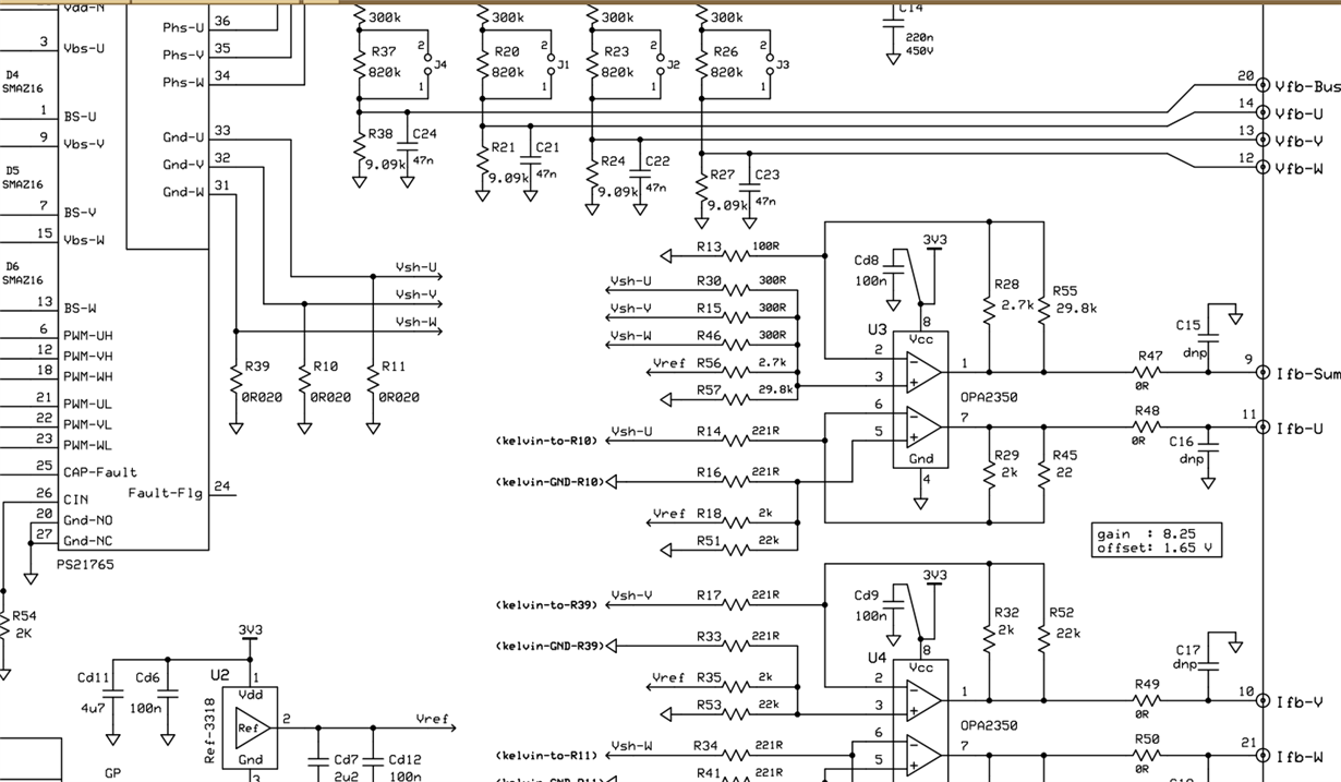
Can you explain the principle of current sampling circuit to me according to the circuit diagram of 28335 motor kit? That is to say, what is the process of converting the actual current into ifb-v?
Best regards
Dear team:
Can you explain the principle of current sampling circuit to me according to the circuit diagram of 28335 motor kit? That is to say, what is the process of converting the actual current into ifb-v?
Best regards
