Other Parts Discussed in Thread: TMS320F28035
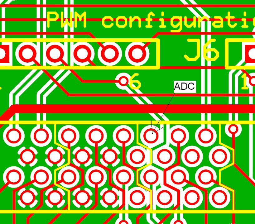
As far as can be judged from tech docs attached to the kit, there is a spare ADC channel onboard.
Where this one can be found?
This thread has been locked.
If you have a related question, please click the "Ask a related question" button in the top right corner. The newly created question will be automatically linked to this question.
Other Parts Discussed in Thread: TMS320F28035
As far as can be judged from tech docs attached to the kit, there is a spare ADC channel onboard.
Where this one can be found?
Just take a look at the picture attached. Here it is named ADC-A5.
How to make use of it correctly?
P.S.: The task is to receive analog waveform from appropriate resistance divider (in order to meet the 0..3.3V requirement) wich is on the external device. GND of that device is the Gnd of kit's board.
Control stick with TMS320F28035 onboard plugged in LV-Multi-Axis w/PFC kitboard .
Thanks.
The question is where to solder or insert wire's end while making minimal changes/cuts in kitboard or control stick.
Thanks.
Look at the attached pic.
What if I solder a wire right on this pin on the back side of the plate?
Thanks.
Maurrey,
The pin you've highlighted is in fact ADC-A5. If you solder a wire onto the pin you should be able to use that ADC channel.
Thank you,
Brett
Actually, addind into main() code construction like that:
Voltage = _IQ15toIQ((AdcResult.ADCRESULT5<<3));
gives 0.0 as a result, (connected wire to the pin shown in previous posts, off course).
What's the matter?
Well, now that channel is selected:
AdcRegs.ADCSOC5CTL.bit.CHSEL = 5;
along with the trigger:
AdcRegs.ADCSOC5CTL.bit.TRIGSEL = 5;
and sample-and-hold time:
AdcRegs.ADCSOC5CTL.bit.ACQPS = 6;
there ARE value changes of Voltage (see previous post).
The question is how to "disconnect" ADC #5 triggering from EPWM1A (AdcRegs.ADCSOC5CTL.bit.TRIGSEL = 5;) and "connect" it with Timer0 (A Tasks) interrupt?
Thanks.