This thread has been locked.

If you have a related question, please click the "Ask a related question" button in the top right corner. The newly created question will be automatically linked to this question.

TMS320F280025: GPIO18 on ControlCard as GPIO

Part Number: TMS320F280025

Hello C2000 Team,

I am using F280025 Control Card and Experimenter kit dock.  I am having trouble getting GPIO18 to work as a GPIO output (I do not have the option of using a different GPIO pin as this is how it will be on customer hardware).

I have already flipped S3 on the control card down to map the GPIO18 to the HSEC header pin 71.  I am running from the internal OSC1.

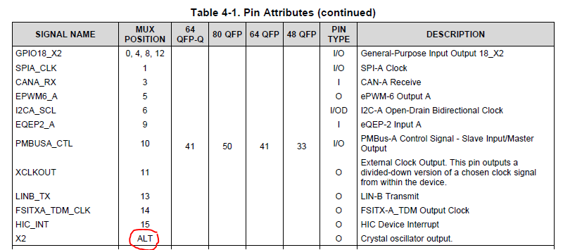
In the datasheet SPRSP45, Table 4-1, it indicates that there is a ALT mux position for this pin.  But there is no information in the datasheet or TRM about configuring (or in my case, not configuring) this function.  I have set the pin muxing for this pin to 0.  But, I cannot get the pin to toggle.

Is there something special I have to do to get this pin to be GPIO?

Thank you,

David

----------------------

6/18/2020 1021AM EDT  Update:

Using CCS, I've attempted to toggle GPIO18 using the Register View window.  I cannot change the value in the GPADAT register for GPIO18 (GPADIR.GPIO18 is set to 1, i.e. output).  I write a 1 to the bit in GPADAT, and it stays as zero.  I tired the same thing for another bit (GPIO7), and I can change GPADAT and also view the change on a scope at the pin.  I also tried GPIO19, and it will not change in GPADAT either.  Something appears to be wrong with GPIO18 and GPIO19.

  • David,

    remember GPADAT will only show the voltage that the input buffer sees on the pin. So if you set GPIO 18 high and it doesn't have enough drive strength to pull it high the DAT register will indicate a 0.(less for your knowledge and more for others)

    I don't have a controlCARD near me right now so:

    • I opened up the Layout and it appears to be connected correctly in the design.
    • Looking further for problems, I looked at the pin map. That too looks to be correct. Showing that these signals connect to pins 71 and 72 of the docking station.

    Can you read the voltage on the pin for a sanity check?

    Can you ohm out that path between the F280025C device pin and the docking station pin with the S3 in both positions?

    If I get the chance I will run to the lab and try and test this.


    Regards,
    Cody 

  • HI Cody,

    I Ohm'd the POST 71 on the dock to the GPIO18 lead on switch S3.  It seems to be working correctly.  Multimeter reads ~0 Ohm in down position, and off scale (infinite) in the up position.

    I also checked the voltage on the POST 71 (GPIO18).  With S3 in up position, I read ~0 volts, which is to be expected.  With S3 in down position, I read ~1.2 V regardless of whether I write a 1 or a 0 to GPADAT bit.

    If you're able to check another board, that would be great.  The board I have is pretty new though, and hasn't had much use.  I would be surprised if it is damaged.  But, you never know.

    Regards,

    David

  • David,

    I have confirmed that on my board I can see both GPIO18 and GPIO19 toggle. This only took GPADIR = 1 and GPAMUXy = 0. Then toggling GPADAT allowed both pins to toggle.

    On my board I see 0V when the GPIOs are configured as inputs and S3 in the down position.

    Can you scope the middle and bottom pins of S3 to see if the 1.2V is coming from the c2000 device or a short somewhere after the switch? Being that we have a 1.2V supply on the board there is a chance that pin is shorted external to the device.

    Can you use the external Xtal on the board?

    Regards,
    Cody 

  • Cody,

    It's great that you were able to test.  Now we know the problem is on my board, and not the device.  This problem will go away when the customer moves to his own board.  At this point, I can move on and just ignor this.  I will order a new control card.

    On your questions:

    I am able to use the on-board XTAL on the control card.

    I checked the S3 voltages.  With GPIO18 configured as an input and S3 up, S3.4 pin shows ~0, while S3.5 pin (the middle pin on right-side) shows ~0.75V.  I don't think we can draw much of a conclusion from this, as S3.5 is connected to the external XTAL in this configuration.  If I put S3 in the down position, both S3.4 and S3.5 read 1.2V (I just re-confirmed).

    ----------

    One last question: what is the 'ALT' in the datasheet pin-muxing tables?  That is, from my first post in this thread, there is no explanation for how to configure for the ALT function.  Does it matter what the GPxMUXy bits are set to?  Seems like we should document this.

    Regards,

    David

  • David,

    One more confirmation, when S3 is in the up position is the value of S3.6 and S3.3? If its 1.2V that would suggest that there is a short somewhere between the HSEC dock and S3. If that is the case I would like to know what is causing it to ensure it isn't a design issue in the PCB which makes these pins susceptible to shorting to 1.2V.

    Do you have any external connections on your docking station? There was a new enhancement where we brought 1.2V down to a previously reserved pin, what revision of the controlCARD do you have?

    Additionally sorry I missed answering that. Taken from the DS:

    "

    GPIO ALT functions cannot be configured with the GPyMUXn and GPyGMUXn registers. These are special functions that need to be configured from the module.

    "

    Regards,
    Cody

  • Hi Cody,

    I just received the new control card I ordered, and it is showing the same problem as the other one.  GPIO18 reads 1.2V and I cannot change the voltage on the pin using the GPADAT register (it always shows a 0).  Same thing for GPIO19.  This is with S3 in down position.  The readings are the same whether I have the pin configured as an input or output in the GPADIR register.

    With switch S3 in the up position, S3.3 reads ~0V, and S3.6 reads ~0.9V.

    Both cards are revision A.

    I have no external connection to the dock.

    I'm not sure what is going on here.  I've rechecked these readings multiple times.

    - David

  • Closing this thread out.  Cody and I worked with the C2000 team and identified the cause of the problem being CAN bootmode.  CAN bootmode requires the external XTAL oscillator, so the bootloader was setting OSCOFF=0 in the XTALCR register (Default setting is 1).  This turns the XTAL oscillator on, which maps the GPIO18 pin over to be the X2 function instead of GPIO.

    On the control card I am using, the bootmode is selected by the S4 switch, which I had mistakenly set for CAN bootmode.  I did not notice this since the debugger was connected.  Setting the bootmode to other than CAN boot resolves the problem with GPIO18.

    Regards,

    David