This thread has been locked.

If you have a related question, please click the "Ask a related question" button in the top right corner. The newly created question will be automatically linked to this question.

CCS: inverter 3p3z current controller

Other Parts Discussed in Thread: SFRA

Tool/software: Code Composer Studio

Hello,

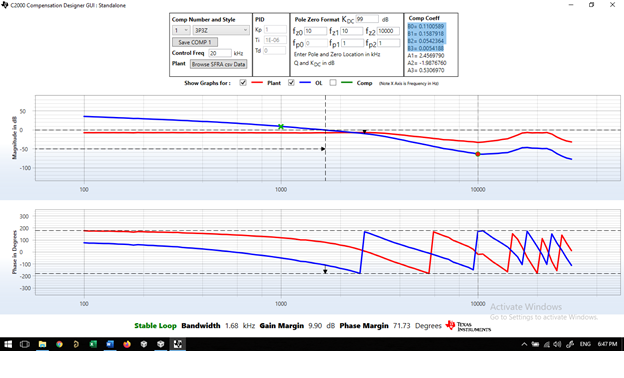
I'm developmenting a inverter grid on, I'm trying to tuning the loop current controller. I used SFRA to obtain the plant model and used the compensator to tuning the controller, but when I use the coefficients in the controller the response doesnt work. I'd like to have a opinion regarding my data from the open loop data. My project has switching frequency 20khz, is based on micro tie grid TMDSSOLARUINVKIT with adaptations.

3404.SFRAData17_June_2020_4_44_28.csv

  • You have to make sure your Bode plot shows a stable system (PM=45 deg min, GM=10dB min) with a reasonable BW. For good tracking of 60Hz/50Hz injected grid current a bandwidth of BW=2kHz or higher should be maintained.

    Also, after you design the first compensator and run the current loop you have to take the Bode plot using SFRA and let the SFRA generate the measured power stage response for you. You save that measured power stage response. Then use the compensation designer again to retune the controller using the measured power stage. Here again you have to make sure that your Bode plot shows a stable system (PM=45 deg min, GM=10dB min) with a BW of at least 2kHz or higher.

    After doing this you use the new controller coefficient (after retuning) in your code as the final set of controller coefficients.

    Shamim

  • Dear Shammin,
    Thanks for the explanation, I think these steps aren't the problem, I need others informations before this, my doubts are:


    1) The 3p3z coeeficients are declared as Q26 in the manual, but in the program they receive Q24 value. is it correct?

    2) I built my board based in the TMDSSOLARUINVKIT_v100 schematic, the AC current and AC voltage have almost 0,4ms of delay, aren't exactly sync, including the sine signal generated, Is this a big problem for the control?

    3) what is the range hoped at 3p3z.out. I did a test, I put the pwm signal to generate the sine wave (build 1) but put the 3p3z controller to work, I plot the AC current and write this peak value in the setpoint, the 3p3z .out move between 0 and 1, I think these out value are high to the calculate of duty_inv_pu (Out + Vgrid/ Vbus). Could you give me tips to understand how this controller need to work, which values are hoped.

    4) At the program "gridconnectedinvlclfltr" the inv_duty is calculated of different form, as Inv_duty = period * (1- abs(inv_duty_pu), for the SOLARUINKIT the calculated is Inv_duty = period * abs(inv_duty_pu). Are these correct for each program?

    Best Regards

    Márcio Bertolani

  • 1. Program uses Q24

    2. Yes, there should not be such huge delay. Delay means you are not pumping real power, i.e. the current is not in phase with voltage.

    3. With Q24, your values can be as high as 127.9999.

    First, the Bode plot needs to show stable control. Once you do that, then take the coefficients whatever it generates under stable condition.

    4. As you can see the first one calculates D' = 1-D and the second one calculates D. So they are correct and depends on how you are applying it to the MOSFETs (main FET or the sync FET)

  • Since you don't have any more question I am assuming this resolves your issue and I can close this case.

  • ok, Thank you for the explanation above!