This thread has been locked.

If you have a related question, please click the "Ask a related question" button in the top right corner. The newly created question will be automatically linked to this question.

CCS/TMS320F280041C: ADC input channel selection

Part Number: TMS320F280041C


Tool/software: Code Composer Studio

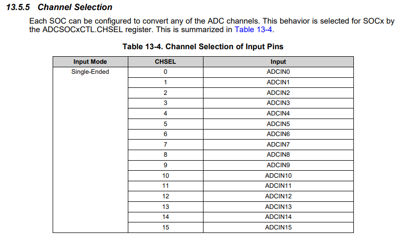
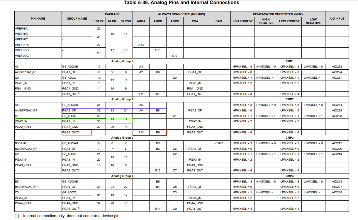
Greetings! I`m using this uC for a very first time and I not very familiar with its peripheral. So I`m watching the examples for adc. I can`t find the connection between the input pin(for example A0, A1, A2 and so on) and the ADC channels. Where do we specify this? How for example do I select the input pin for the ADC conversion to be A0 input? Is there any table? In which document?

Thanks!

  • Hi,

    Which board are you using? Is it controlcard or launchpad?

    Thanks
    Vasudha

  • I am using my board! I am using pin 40(A10)  as analog input!

    Thanks!

  • Hi Pavlin,

    You'll want to start with the ADC chapter in the device TRM (https://www.ti.com/lit/ug/sprui33c/sprui33c.pdf?ts=1593693124759).

    The CHSEL field in the SOC logic controls the channel selection:

    And then note that results are stored by SOC number, not by channel number, so the results of SOC0 will be stored in ADCRESULT0 regardless of channel selection. 

    e.g. ADCA->SOC0->CHSEL = 2 will store the results from sampling A2 in ADCA->ADCRESULT0

    e.g. ADCA->SOC1->CHSEL = 0 will store the results from sampling A0 in ADCA->ADCRESULT1

  • Ok! One more question! I`ve noticed that when I apply 0 voltage to the ADC pin it measures 322. Which I think is about 0.4V. I`ve measured with my oscilloscope around 0.120V ripple because the pin is unconnected now. Is this normal? I am just testing the PCB.

    Thanks!

  • Sorry, this was my fault! I had a problem with the reference voltage. Now it works fine!

    But how to MUX the PGA inputs. I`m looking at the pga_ex1_dac_adc_ext_loopback example. There is selected PGA2_IN. The problem is in my case the row [code]

    pgaResult = ADC_readResult(ADCARESULT_BASE, ADC_SOC_NUMBER1);

    [/code]

    doesn`t work! I have a pinout to all PGA inputs but noone seem to work - follow the changes on the input. Rather that the analog input A10 is working correctly.

    I`ve tried with different selected channel -> ADC_CH_ADCIN11,ADC_CH_ADCIN5 and so on. No change. 

    Do I have to select the PGA channel somewhere else? There is nothing in the example func initPGA connected to the MUX.

    Thanks!

  • Hi Pavlin,

    For each PGA, there will be 1 input pin (green).  You then need to enable the PGA output and read the PGA through the internal-only ADC input (red).  Alternately, you can route the PGA output to a pin so that you can add some capacitance for filtering purposes (blue).  This will result in needing to use a different input pin (blue).