This thread has been locked.

If you have a related question, please click the "Ask a related question" button in the top right corner. The newly created question will be automatically linked to this question.

TMS320F28069M: InstaSPIN: distorted phase currents when using current reconstruction

Part Number: TMS320F28069M

Hello,

We are using the current reconstruction algorithm from lab 10a - An Example in Space Vector Over Modulation and we saw that the currents on each phase is distorted when reaching 3000RPM on a BLDC motor with a maximum speed of 3750 RPM.

Here are the plots of the phases at different speeds (1000RPM, 2000RPM and 3000RPM):

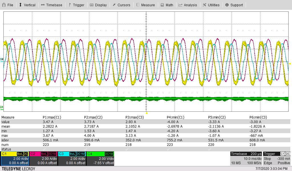
Q1: I'd like to know if such kind of "distortion" is foreseeable in current reconstruction?

Q2: If this "distortion" is abnormal, what could be the cause?

For your information, we did not bring any modification to the current reconstruction algorithm from Lab 10a.

Thank you for your support.

Regards

  • What value is the USER_MAX_VS_MAG_PU? YOu may set USER_MAX_VS_MAG_PU to a value that's less than 0.5774 = 1/SQRT(3). If the value is greater than 0.5774, the current sensing circuit will require very high signal quality and need to set a very low ADC sampling window in the ADC configuration function.

  • Our USER_MAX_VS_MAG_PU is (2.0 / 3.0).

    At the beginning, we were using 0.5 for USER_MAX_VS_MAG_PU but were not able to reach about 50% of the speed of our motor (motor maximum speed = 5000 RPM, maximum speed with 0.5 was 2500 RPM).

    Q: As I've understood, when facing limited motor speed range (due to FOC), the only way to increase maximum motor speed is to increase the voltage applied to the motor (which is not possible in our case) or increase USER_MAX_VS_MAG_PU parameter. Is this right? Or is there another way to increase this maximum speed limitation caused by the FOC?

  • Please set the USER_MAX_VS_MAG_PU to a value of less than 0.5774=1/SQRT(3). If no, the current sensing signals will be very critical, and the dead-time should be very small. 

    You might implement the field weakening control to achieve the high speed if the load of the motor does not increase with the speed.

  • Any updates? We would like to close this thread if no any further questions. Thanks.


  • I have to check if field weakening is possible with the load we have.

    Q1: You say that current sensing circuit will require very high signal quality. Can you detail a little bit more what you mean by "very high signal quality"?

    Indeed, in our design, we use the current sensing circuit of the DRV8353S in order to measure each phase current in a low-side resistor topology. The C2000 ADC sample window is already at the lowest value of 7 cycles.

  • That depends on the PCB layout design to avoid noise as low as clear as possible on the sampling signals.

    You might limit the USER_MAX_VS_MAG_PU to 0.5774=1/SQRT(3) which should be ok for most cases.