


Part Number: TMS320F28054F
Tool/software: Code Composer Studio
I have two boards. One uses ADC B0, B2, B3 to read current from the 3 phases. This board works perfectly, and I can control the speed of the motor easily. Here's the phase current switching when the motor is not spinning (target speed = 0 rpm):
 The other board uses ADC A1, B3, B1 to read current. This is done to make use of the analog comparators, but those are not being used at the moment. This current sensor signal comes in as 1/3 of the value on the other board such that the gain of 3 on these ADC pins can be applied. I can see in the ADC registers that this all works correctly.
When I try to run the exact same program (a modified version of instaspin foc lab 5b) on this board, the only change I make is in moving the ADC current pins in hal.c. When I run the program, it trips for any target speed > 0. When I hold it at 0 rpm, I see this waveform: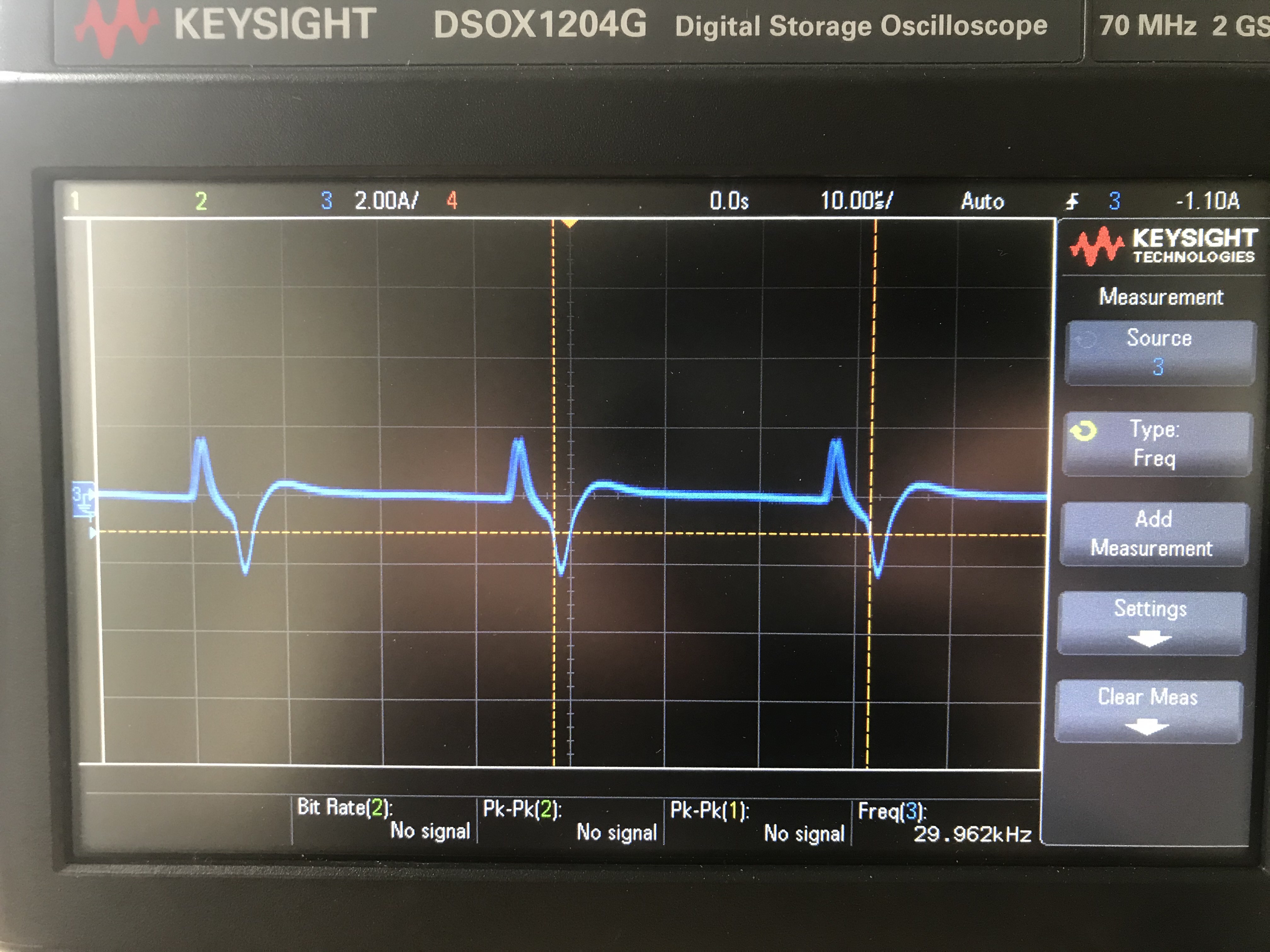 I cannot find any issues in hardware that could be causing this. To me it seems that the deadband time differs, but I believe this is set and unchanged in the project. Could there be some floating point value causing this discrepancy?
