Tool/software: TI C/C++ Compiler
Thank you very much for your attention!
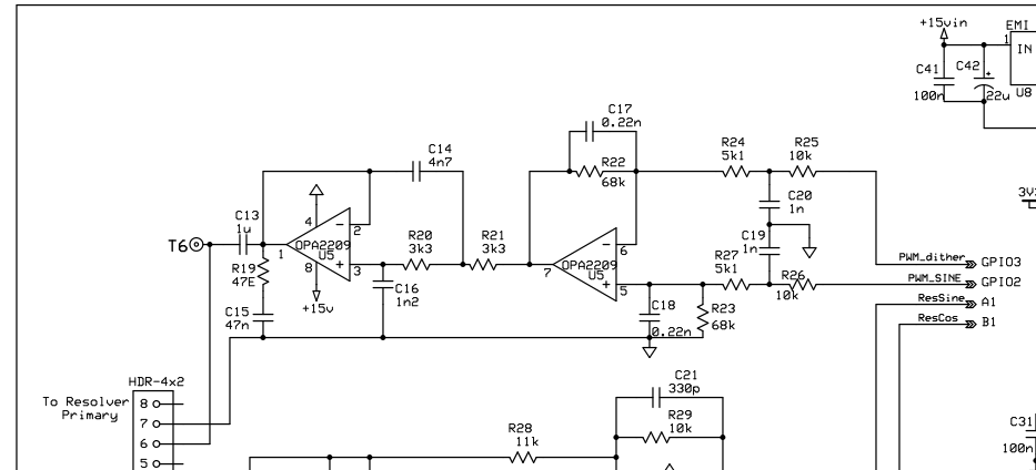
1. In the resolver excitation circuit above, the power supply of the operational amplifier is 15V. Can this voltage be reduced?
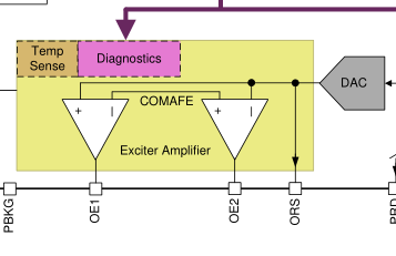
2. In the application of pga411, the negative excitation winding of the resolver is connected to the exciter amplifier negative output, as shown in the figure below. But why is the negative excitation winding of the resolver connected with GND in the above figure? What is the difference between the two types of circuit structure?


