This thread has been locked.

If you have a related question, please click the "Ask a related question" button in the top right corner. The newly created question will be automatically linked to this question.

TMS320F28379D: 100kHz ADC

Part Number: TMS320F28379D
Other Parts Discussed in Thread: C2000WARE

Hello,

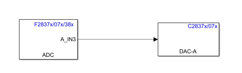
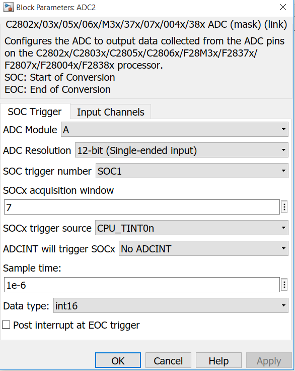
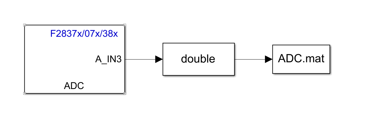
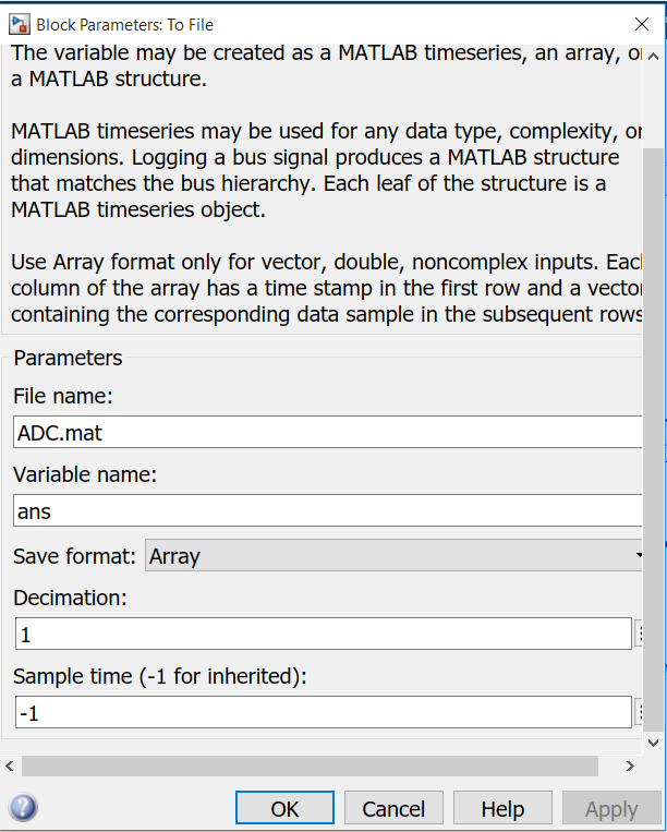
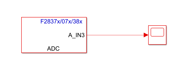
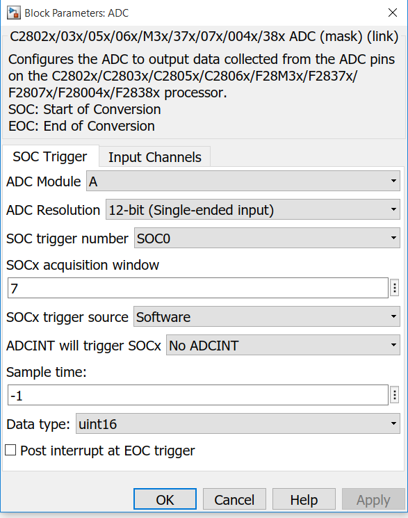
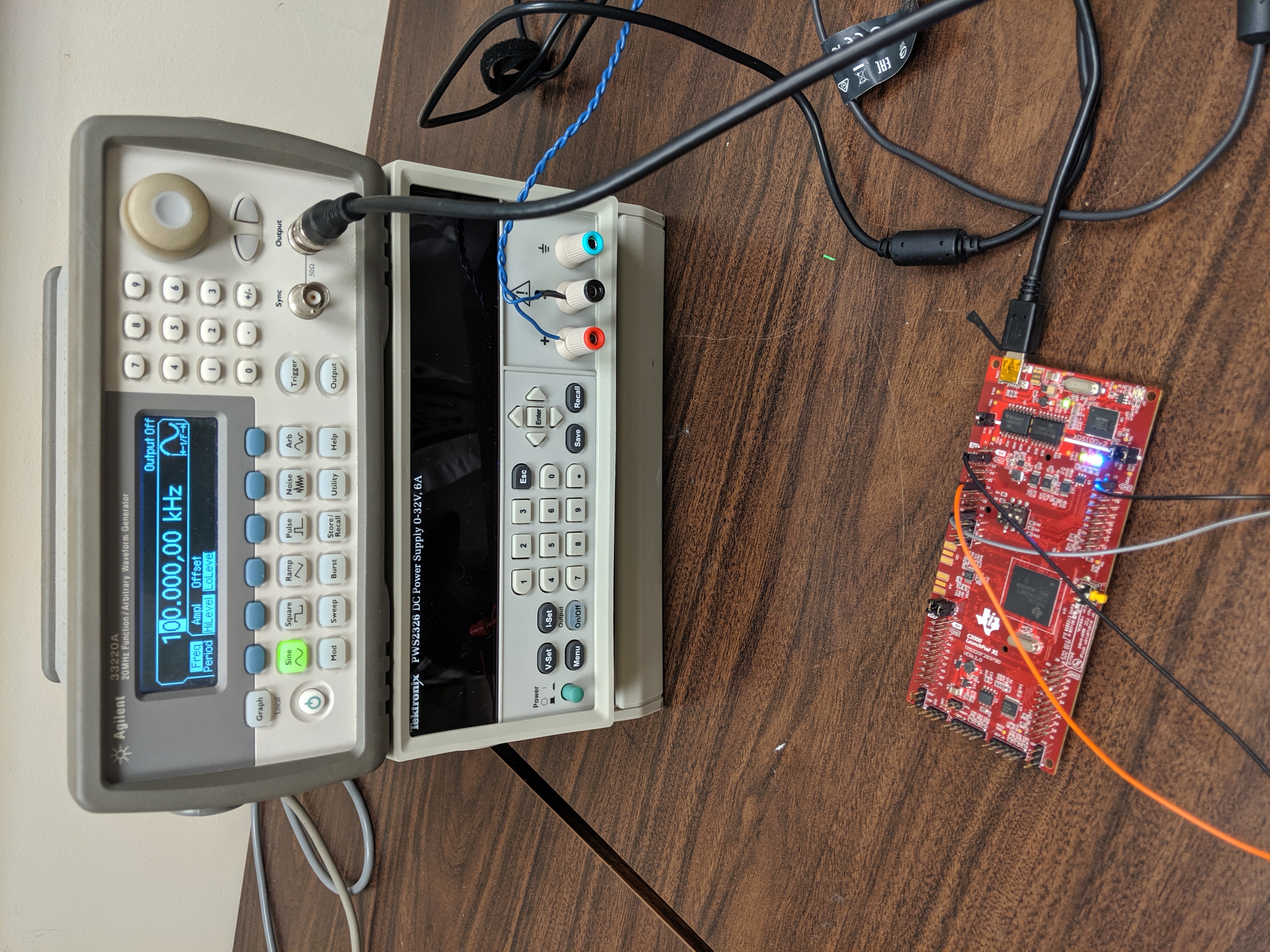
I am reading an analog signal at 100kHz. I use the sample time: 1e-6 and got the waveform as below. However, I cannot reduce my sample time. For example, if I enter 1e-7, there is no waveform any more on my oscilloscope. May I ask for some help to get a nice 100kHz waveform?

Thank you,

Alice

  • Hi Alice,

    What is the source of the 100kHz signal that you are converting?  Is it generated from the internal DAC of the F28379D chip?  In the scope capture shown, is that probed At the input of the ADC?

    Regards,

    Joseph  

  • Hello Joseph,

    The source of 100kHz signal is from my function generator. The output on my oscilloscope is measured from the output of DAC channel A.

    Thank you,

    Alice

  • Hi Alice,

    Can you decouple the DAC from your measurement for the time being?  Just wanted to see what is causing the distorted 100kHz signal that is displayed in the scope.  Just do an ADC conversion of the signal from the func gen that is fed to the ADC and send the converted data as an array.

    Thanks,

    Joseph 

  • Hello Joseph,

    Thank you for your reply. Since I never try to save the data of ADC as an array. May I ask for some help on how to save it? I am not sure whether my approach is what you are asking.

    Thank you,

    Alice

  • Hi Alice,

    Yes, this is what I am looking for,  Just accumulate the converted ADC readings (in the double box) and store them in sequential order.  a few hundred samples will do.  We should be able to recreate the converted waveform with this data.

    Regards,

    Joseph

  • Hi Joseph,

    I run my model in external mode so that I can plot directly from the Simulink scope. I set the sample time -1 for both ADC and scope block. The external mode only works with solver step size: auto. Otherwise, it will give me error: target not connected/ timeout...

    Thank you,

    Best Regards,

    Alice

  • Hi Alice,

    Not familiar with your interface but looks like this is MATLAB/Simulink tool.  Anyway, sampling window set to 7 is the lowest setting, which should work, but then you are only getting 6 conversions per cycle.  Seems like the system clock for the F28379D is way too slow.  Any way you can confirm what your clock settings are?  If you configure the system clock to 200MHz and ADC prescale divider of 6 (ADCLK=SYSCLK/4), you should be able to have about 36 samples per cycle of the 100kHz signal.

    Regards,

    Joseph

  • Hi Joseph,

    The default prescale is 5 and I even tried to reduce the prescale to 2. The results are the same.

    Thank you,

    Alice

  • Hi Alice,

    ADC connote be clocked at 100MHz.  Per spec, ADC can only be clocked at 50MHz max.  Also, how do you configure the sampling rate in your set up?

    Regards,

    Joseph

  • Hi Joseph,

    I change the ADC clock to 50MHz. Are you asking the source of my analog? It is from the function generator directly. I didn't configure anything in my setup. And the analog goes to ADCAIN channel 3.

    Thank you for your patience,

    Alice

  • Hi Joseph,

    Hope you are doing well. Do you think the problem is from the MATLAB interface rather than the microcontroller itself? Suppose I purchase a faster TI microcontroller, the results can be exactly the same, right? Because it is better for me to see this 100kHz signal in real time for my project, I am thinking of any other options I can have. Any suggestions?

    Thank you,

    Best Regards,

    Alice

  • Hi Alice,

    Thanks, i'm doing fine and hope you are too!  I am not familiar with your setup but it seems like your system has a F28379D micro-controller that is interfaced with Matlab to setup the F28379D configurations (clock, ADC, DAC, etc...).  The F28379D should be able to sample a 100kHz with no issues.  It is likely that the interface with Matlab prevents you from properly configuring the ADC to sample the desired signal.  One option you can try, if possible is to decouple the F28379D from Matlab and configure everything from Code Composer Studio and XDS emulator.  You can then use the ADC conversion/setup examples in C2000Ware to capture the 100kHz signal you wanted to sample.

    Regards,

    Joseph