This thread has been locked.

If you have a related question, please click the "Ask a related question" button in the top right corner. The newly created question will be automatically linked to this question.

CCS/TMS320F28379D: What changes I need to do in the code and in which files for changing or manipulating the EPWM GPIO pin for this Launchpad

Part Number: TMS320F28379D
Other Parts Discussed in Thread: CONTROLSUITE, C2000WARE, POWERSUITE

Tool/software: Code Composer Studio

Hello There

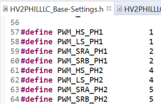
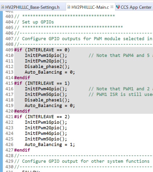
I am working on 2 phase interleaved LLC converter, C:\ti\controlSUITE\development_kits\TIDM_1001\v1_00_00_00\f2837x\HV2PHILLLC. In the TI document, they are performing the code in the control card. I am willing to perform this into Launchpad just to observe EPWM. For that where should I change the EPWM in the code? I will only connect Launchpad, will not connect the TIDM 1001 because only focus on EPWM signals now.

Thanks

Avi

  • You are using ControlSuite and not C2000WARE?

  • Yes, I am using ControlSUIT. I am new to TI. Am I on the wrong track?

    Actually I have started with Control Card and ultimately will use the control card but for safety purposes, for analyzing the EPWM I m trying to use the same controlSUIT in Launchpad.

  • Hi Avi,


    I'm sorry you're having trouble with the controlCARD route. Are you using a docking station with the controlCARD? https://www.ti.com/tool/TMDSHSECDOCK

    Are you having any specific problems with the LaunchPad? Are you able to load the code, but you can't observe the PWM signals? I can't think of any specific modifications you will need to make to get this code working with a Launchpad, but I will try to run it on my end and see if everything works.

    ControlSUITE is an older product that we no longer actively develop, and it has been replaced by C2000Ware and the Digital Power SDK. It's probably better to use the Digital Power SDK if possible, but if you want to use the F28379D device then you will have to use ControlSUITE to get started because we only support F28004x for this LLC example in the Digital Power SDK.

    Best,

    Clayton

  • Thank you Clayton for a brief explanation. Yes, I am using controSUIT because of no example of LLC for F28379D. Yes As per this C:\ti\controlSUITE\development_kits\TIDM_1001\v1_00_00_00\f2837x\HV2PHILLLC project, TI suggests to use Control Card and I using that docking station (180 pins). So What I am trying to do to run the code into Launchpad instead control card to just see the PWM waveform. If its work then I can manage that without high voltage and it would be good for safety purpose. No worries you can try at your end and please let me know if you require any further information.

  • Also another question regarding the Location of GPIO for EPWM. How to change the GPIO pins for EPWM, what procedure I need to follow? It must be through changing into code right?  

  • Hi Avi,

    You do not need high voltage to run this example on the controlCARD.

    If you prefer to proceed with the LaunchPAD for now, I am able to run the code and observe the PWMs on the launchpad with no modifications to the project.

    You will need to load the code onto the launchpad, ground pins 29, 67, 69 to prevent floating voltages from causing the device to go into over current protection mode, and set the start_flag variable equal to 1 in the CCS watch window to start the converter and reset and spurious trip.

    You should be able to probe one of the PWM signals on pin 40.

    This project doesn't support changing the PWM assignment through the powerSUITE dialog, but if you want to change that PWM assignments there are three things to consider:

    1. You will need to consider how the PWM synchronization happens and update the links between the EPWM modules (see section 15.4.3.3 Time-Base Counter Synchronization, of the TRM)
    2. You will need to update the PWM selection in the HV2PHILLLC_Base-Settings.h file.
    3. You will need to change the PWM selection in the  GPIO mux to select the PWM setting, see section 8.7 GPIO and Peripheral Muxing of the TRM. You can see an example of how this is done in the code for this project. You can also refer to the GPIO setup in the HV2PHILLLC-Main.c file.

    Best,

    Clayton