This thread has been locked.

If you have a related question, please click the "Ask a related question" button in the top right corner. The newly created question will be automatically linked to this question.

CCS/TMS320F28379D: Spikes on ADC_measurement

Part Number: TMS320F28379D

Tool/software: Code Composer Studio

Hi Everyone

I'm using the ADC to read values, but i have the following problem:

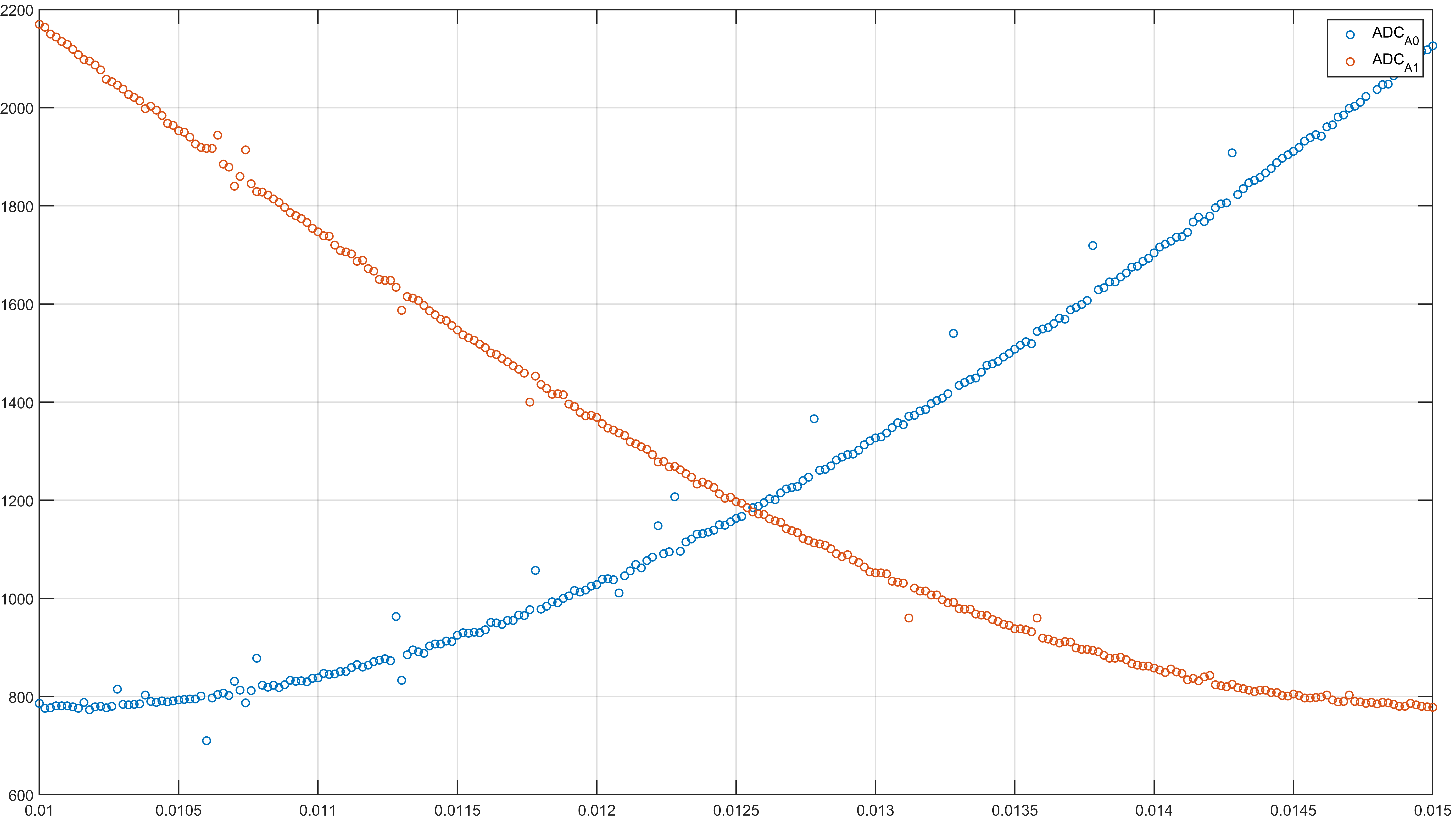
Currently, i'm reading the adc periodically, with a 50khz of sample rate. But i have this spikes, I don't know where they come from, and I don't know how to fix them either, since that affects the dynamics of the control that I will apply later.

Any idea how to fix this? Or is it something to be expected?

I am feeding the system with a signal from a signal generator (photo 3), then I read the data from the adc and export the data and plotting it (photo 1), in photo 2, can see the zoom that I made to the signal.

  • Hi Matias,

    It doesn't look like your pictures came through.

    If you are seeing some noise in the ADC output, some things to look at:

    • Is the signal buffered locally on the PCB by a low-noise high bandwidth op-amp?
    • If not, what is the impedance of the driver? Is there any RC on the pin?
    • What is the S+H duration? Is this long enough given the input impedance?
    • What is driving the VREFHI pin?  Is it a clean low-noise DC voltage driven by a high-bandwidth op-amp?
    • What is the ADCCLK?  Are you sure it is set to 50MHz or less?
    • What is the SYSCLK? Are you sure it is 200MHz or less?
    • Are you sure the various device supply voltages are within the operating ranges?

  • Hi Devin,

    Devin Cottier said:

    It doesn't look like your pictures came through.

    This are the photos:

    Devin Cottier said:
    • Is the signal buffered locally on the PCB by a low-noise high bandwidth op-amp?

    No, im using the Delfino F28377D controlCARD to get signals from the waveform generator (Digilent Analog Discovery 2)

    Devin Cottier said:
    • If not, what is the impedance of the driver? Is there any RC on the pin?

    Nop, i'm not using any RC, im connecting directly from the generator to the ControlCARD

    Devin Cottier said:
    • What is the S+H duration? Is this long enough given the input impedance?

    the S+H is 1[us] -> acqps 200, the TMR say it should be greather than 75, so, 200 its fine i think

    Devin Cottier said:
    • What is driving the VREFHI pin?  Is it a clean low-noise DC voltage driven by a high-bandwidth op-amp?

    VREFHI pin has not been modified, so, the adc only get values from 0 to 3 [V] (is the 12-bit adc, from 0 to 4095 counts)

    Devin Cottier said:
    • What is the ADCCLK?  Are you sure it is set to 50MHz or less?

    Yes, is 50MHz (with prescale bits)

    Devin Cottier said:
    • What is the SYSCLK? Are you sure it is 200MHz or less?

    This is not been modified, so, it should be 200MHz.

    Devin Cottier said:
    • Are you sure the various device supply voltages are within the operating ranges?

    Currently, because COVID19, i'm working from home, and the analog discovery 2 and the Delfino F28377D are the devices that i'm using, so, at the moment I can only trust in TI and Digilent.

    Thanks for u reply

  • Hi Matias,

    Whatever error you are getting is very large and also seemingly periodic, so there seems to be an issue with noise coupling into the signal.

    What does the cabling look like for connecting your signal to the board?

    Normally you would want some R-C on the ADC input pin with C approximately 20 x Csh (about 20 x 14.5pF = 290pF) and some nominal R in the 10s of ohms (see https://training.ti.com/node/1139106?context=1139106).  Even better if you can locally buffer the signal on the PCB with an op-amp.  

    You might try a different channel than A0/A1; these channels have a parasitic ~50kohm pulldown due to muxing with the buffered DAC output.