


Other Parts Discussed in Thread: CONTROLSUITE, C2000WARE
Tool/software: Code Composer Studio
Hi e2e Team.
I am trying to send data from MCU TMS320F28377S to PC via USB UART TTL. This is my setup system:
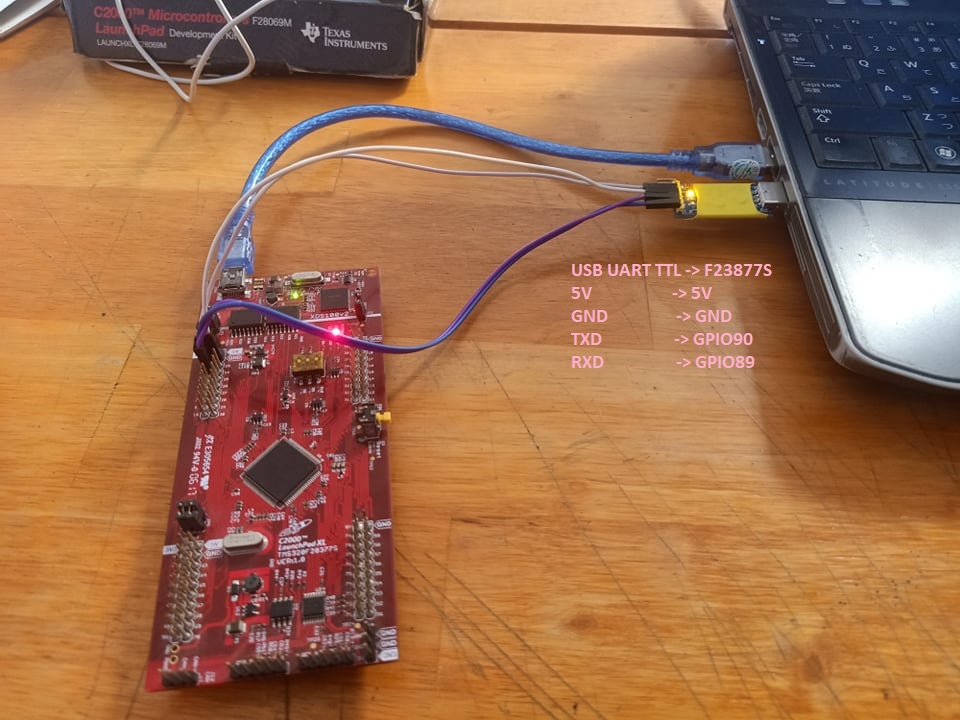
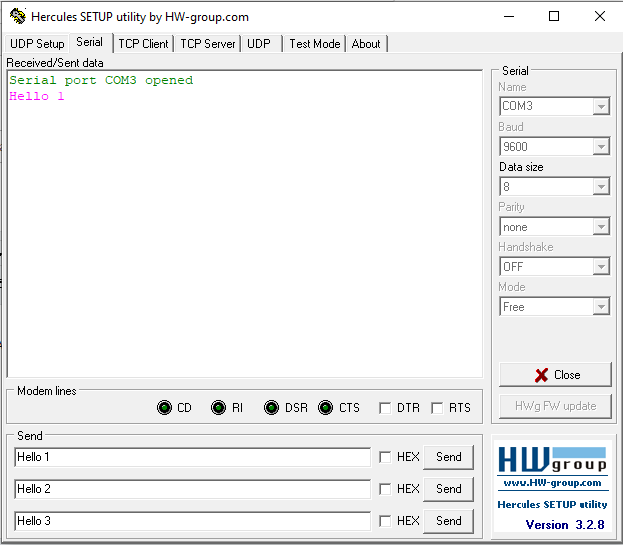
I use Herculus software to read and write data from MCU. I configured COM3 = USB UART, Data size = 8 and baud rate = 9600.
I flow to the example sci_echoback (\ti\controlSUITE\device_support\F2837xS\v210\F2837xS_examples_Cpu1\sci_echoback\cpu). Then I edited the code configured GPIO:
GPIO_SetupPinMux(90, GPIO_MUX_CPU1, 6);
GPIO_SetupPinOptions(90, GPIO_INPUT, GPIO_PUSHPULL);
GPIO_SetupPinMux(89, GPIO_MUX_CPU1, 6);
GPIO_SetupPinOptions(89, GPIO_OUTPUT, GPIO_ASYNC);
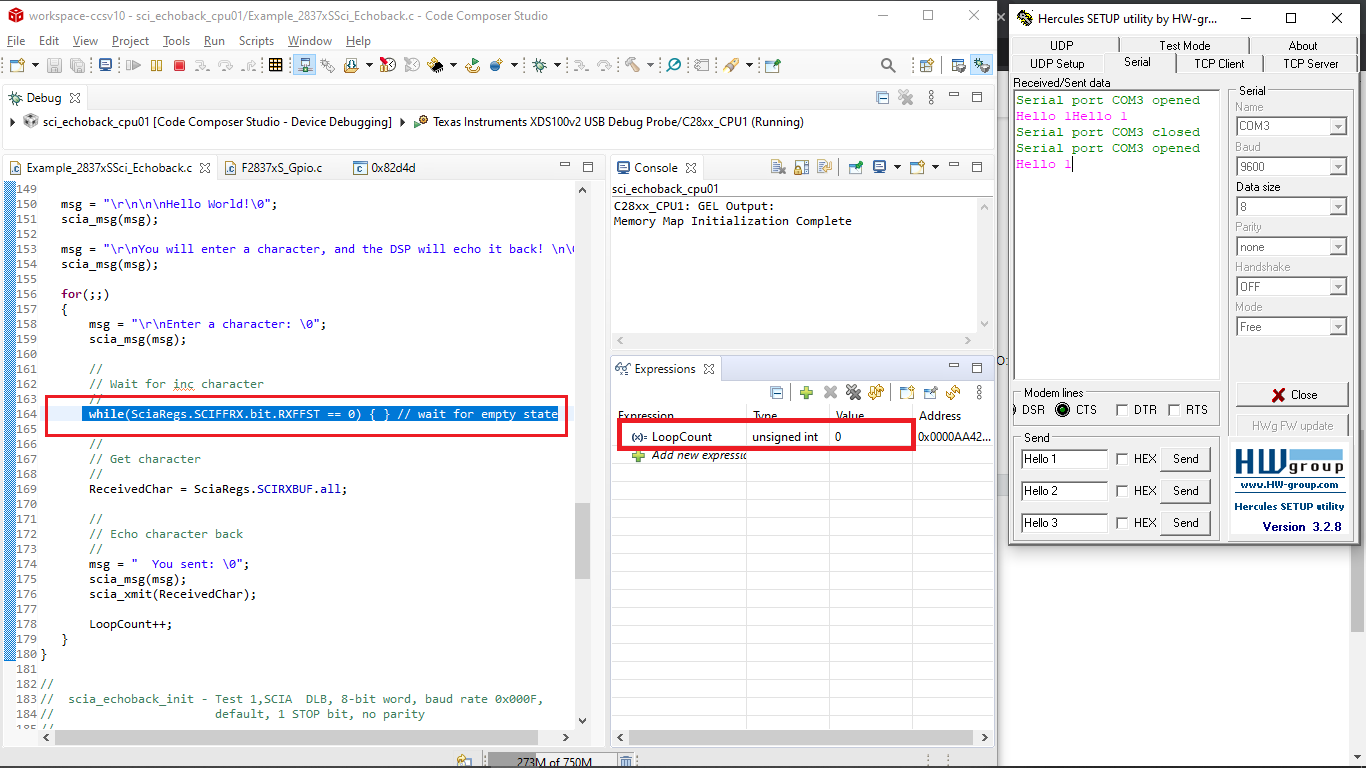
But when I try to send data from Hercules, there are nothing happening: LoopCount = 0, the program stop at line 164: while(SciaRegs.SCIFFRX.bit.RXFFST == 0) { }.
Please help me to send data from MCU to PC via USB UART.
Thank you.
This is my full main.c:
//###########################################################################
//
// FILE: Example_2837xSSci_Echoback.c
//
// TITLE: SCI Echoback.
//
//! \addtogroup cpu01_example_list
//! <h1>SCI Echoback (sci_echoback)</h1>
//!
//! This test receives and echo-backs data through the SCI-A port.
//!
//! The PC application 'hyperterminal' or another terminal
//! such as 'putty' can be used to view the data from the SCI and
//! to send information to the SCI. Characters received
//! by the SCI port are sent back to the host.
//!
//! \b Running \b the \b Application
//! -# Configure hyperterminal or another terminal such as putty:
//!
//! For hyperterminal you can use the included hyperterminal configuration
//! file SCI_96.ht.
//! To load this configuration in hyperterminal
//! -# Open hyperterminal
//! -# Go to file->open
//! -# Browse to the location of the project and
//! select the SCI_96.ht file.
//! -# Check the COM port.
//! The configuration file is currently setup for COM1.
//! If this is not correct, disconnect (Call->Disconnect)
//! Open the File-Properties dialogue and select the correct COM port.
//! -# Connect hyperterminal Call->Call
//! and then start the 2837xS SCI echoback program execution.
//! -# The program will print out a greeting and then ask you to
//! enter a character which it will echo back to hyperterminal.
//!
//! \note If you are unable to open the .ht file, or you are using
//! a different terminal, you can open a COM port with the following settings
//! - Find correct COM port
//! - Bits per second = 9600
//! - Date Bits = 8
//! - Parity = None
//! - Stop Bits = 1
//! - Hardware Control = None
//!
//! \b Watch \b Variables \n
//! - LoopCount - the number of characters sent
//!
//! \b External \b Connections \n
//! Connect the SCI-A port to a PC via a transceiver and cable.
//! - GPIO28 is SCI_A-RXD (Connect to Pin3, PC-TX, of serial DB9 cable)
//! - GPIO29 is SCI_A-TXD (Connect to Pin2, PC-RX, of serial DB9 cable)
//!
//
//###########################################################################
// $TI Release: F2837xS Support Library v200 $
// $Release Date: Tue Jun 21 13:52:16 CDT 2016 $
// $Copyright: Copyright (C) 2014-2016 Texas Instruments Incorporated -
// http://www.ti.com/ ALL RIGHTS RESERVED $
//###########################################################################
//
// Included Files
//
#include "F28x_Project.h"
//
// Globals
//
Uint16 LoopCount;
//
// Function Prototypes
//
void scia_echoback_init(void);
void scia_fifo_init(void);
void scia_xmit(int a);
void scia_msg(char *msg);
//
// Main
//
void main(void)
{
Uint16 ReceivedChar;
char *msg;
//
// Step 1. Initialize System Control:
// PLL, WatchDog, enable Peripheral Clocks
// This example function is found in the F2837xS_SysCtrl.c file.
//
InitSysCtrl();
//
// Step 2. Initialize GPIO:
// This example function is found in the F2837xS_Gpio.c file and
// illustrates how to set the GPIO to it's default state.
//
InitGpio();
//
// For this example, only init the pins for the SCI-A port.
// GPIO_SetupPinMux() - Sets the GPxMUX1/2 and GPyMUX1/2 register bits
// GPIO_SetupPinOptions() - Sets the direction and configuration of the GPIOS
// These functions are found in the F2837xS_Gpio.c file.
//
GPIO_SetupPinMux(90, GPIO_MUX_CPU1, 6);
GPIO_SetupPinOptions(90, GPIO_INPUT, GPIO_PUSHPULL);
GPIO_SetupPinMux(89, GPIO_MUX_CPU1, 6);
GPIO_SetupPinOptions(89, GPIO_OUTPUT, GPIO_ASYNC);
//
// Step 3. Clear all __interrupts and initialize PIE vector table:
// Disable CPU __interrupts
//
DINT;
//
// Initialize PIE control registers to their default state.
// The default state is all PIE __interrupts disabled and flags
// are cleared.
// This function is found in the F2837xS_PieCtrl.c file.
//
InitPieCtrl();
//
// Disable CPU __interrupts and clear all CPU __interrupt flags:
//
IER = 0x0000;
IFR = 0x0000;
//
// Initialize the PIE vector table with pointers to the shell Interrupt
// Service Routines (ISR).
// This will populate the entire table, even if the __interrupt
// is not used in this example. This is useful for debug purposes.
// The shell ISR routines are found in F2837xS_DefaultIsr.c.
// This function is found in F2837xS_PieVect.c.
//
InitPieVectTable();
//
// Step 4. User specific code:
//
LoopCount = 0;
scia_fifo_init(); // Initialize the SCI FIFO
scia_echoback_init(); // Initialize SCI for echoback
msg = "\r\n\n\nHello World!\0";
scia_msg(msg);
msg = "\r\nYou will enter a character, and the DSP will echo it back! \n\0";
scia_msg(msg);
for(;;)
{
msg = "\r\nEnter a character: \0";
scia_msg(msg);
//
// Wait for inc character
//
while(SciaRegs.SCIFFRX.bit.RXFFST == 0) { } // wait for empty state
//
// Get character
//
ReceivedChar = SciaRegs.SCIRXBUF.all;
//
// Echo character back
//
msg = " You sent: \0";
scia_msg(msg);
scia_xmit(ReceivedChar);
LoopCount++;
}
}
//
// scia_echoback_init - Test 1,SCIA DLB, 8-bit word, baud rate 0x000F,
// default, 1 STOP bit, no parity
//
void scia_echoback_init()
{
//
// Note: Clocks were turned on to the SCIA peripheral
// in the InitSysCtrl() function
//
SciaRegs.SCICCR.all = 0x0007; // 1 stop bit, No loopback
// No parity,8 char bits,
// async mode, idle-line protocol
SciaRegs.SCICTL1.all = 0x0003; // enable TX, RX, internal SCICLK,
// Disable RX ERR, SLEEP, TXWAKE
SciaRegs.SCICTL2.all = 0x0003;
SciaRegs.SCICTL2.bit.TXINTENA = 1;
SciaRegs.SCICTL2.bit.RXBKINTENA = 1;
//
// SCIA at 9600 baud
// @LSPCLK = 50 MHz (200 MHz SYSCLK) HBAUD = 0x02 and LBAUD = 0x8B.
// @LSPCLK = 30 MHz (120 MHz SYSCLK) HBAUD = 0x01 and LBAUD = 0x86.
//
SciaRegs.SCIHBAUD.all = 0x0002;
SciaRegs.SCILBAUD.all = 0x008B;
SciaRegs.SCICTL1.all = 0x0023; // Relinquish SCI from Reset
}
//
// scia_xmit - Transmit a character from the SCI
//
void scia_xmit(int a)
{
while (SciaRegs.SCIFFTX.bit.TXFFST != 0) {}
SciaRegs.SCITXBUF.all =a;
}
//
// scia_msg - Transmit message via SCIA
//
void scia_msg(char * msg)
{
int i;
i = 0;
while(msg[i] != '\0')
{
scia_xmit(msg[i]);
i++;
}
}
//
// scia_fifo_init - Initialize the SCI FIFO
//
void scia_fifo_init()
{
SciaRegs.SCIFFTX.all = 0xE040;
SciaRegs.SCIFFRX.all = 0x2044;
SciaRegs.SCIFFCT.all = 0x0;
}
//
// End of file
//
